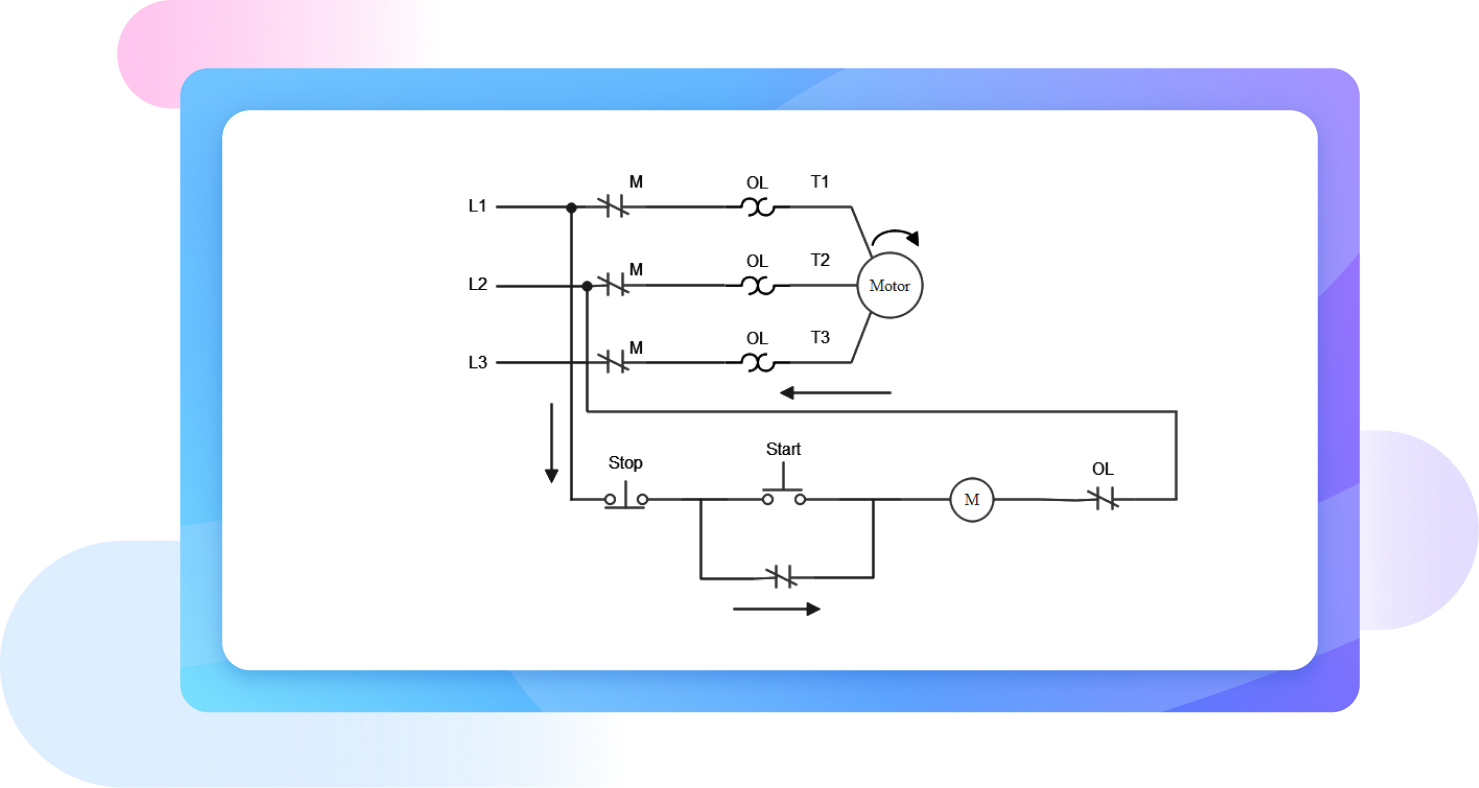
Free ladder diagram maker

Experience excellence with EdrawMax: Your ultimate alternative to CAD and Visio. Explore a vast collection of templates and symbols designed for making ladder diagrams with ease and precision.

banner banner

Best alternative for CAD software and Visio

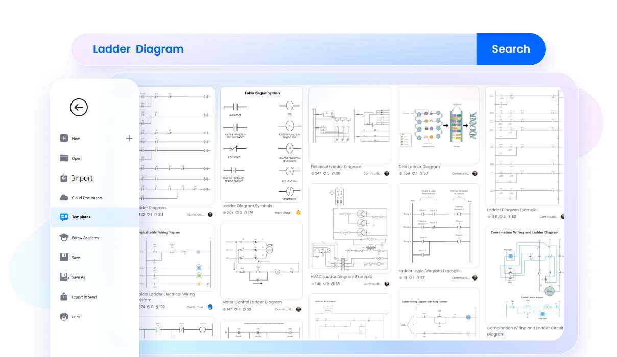
15,000+ templates for all diagram types
Dive into a world of creativity with over 15,000 templates for every diagram type. EdrawMax turns your ideas into stunning visuals, effortlessly.
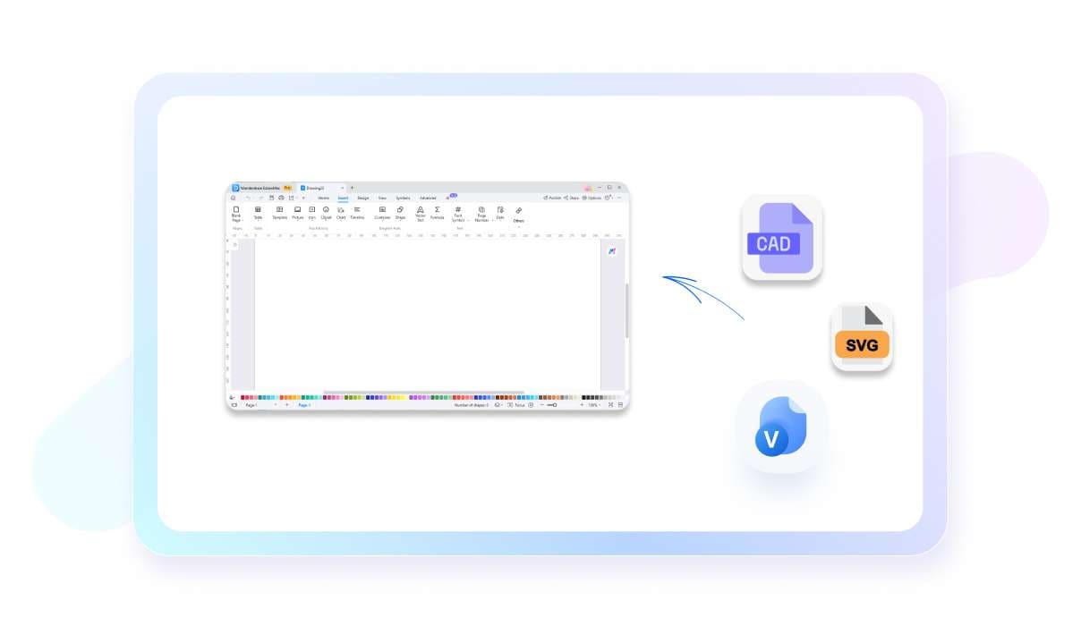
Import CAD, Visio, SVG files at ease
Import from CAD, Visio, SVG with unparalleled ease. EdrawMax bridges your work across platforms, enhancing your design flow.
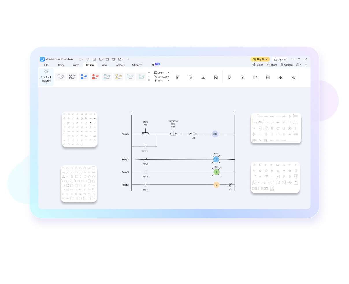
Unrivaled Symbol Library
Access a treasure trove of 26,000 symbols. EdrawMax enriches your diagrams with endless possibilities, making each creation unique.
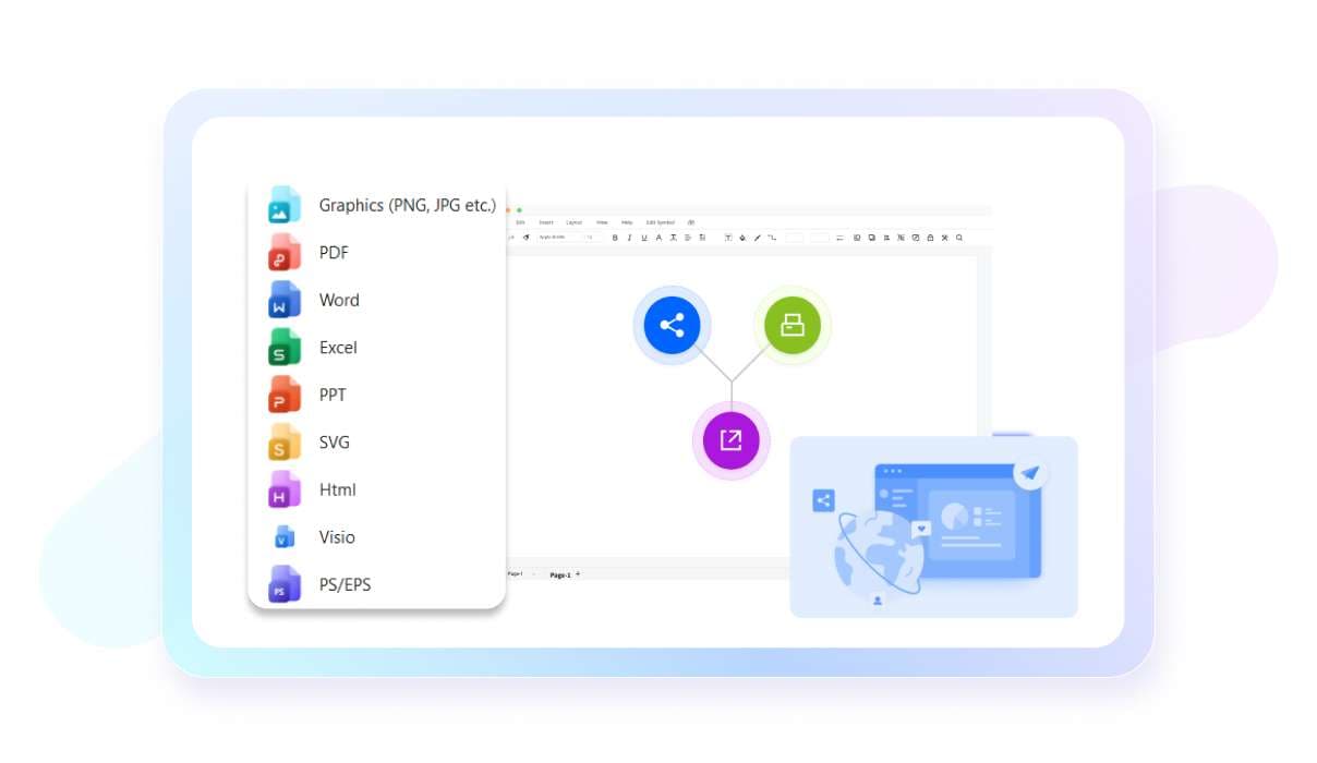
Export files in SVG, Visio, and other formats
Transform and share your diagrams in SVG, Visio, and more. EdrawMax ensures your work is compatible and presentable, wherever it goes.
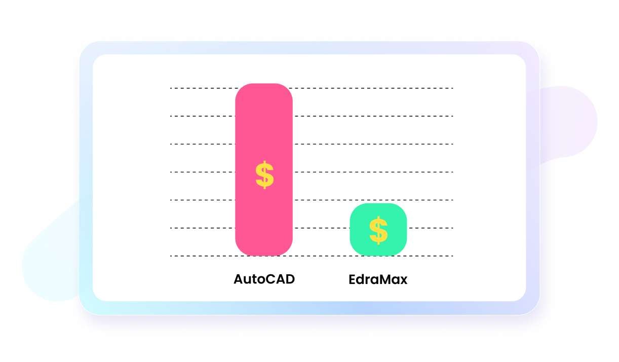
Excellent experience, lower price
Experience premium diagramming at an more affordable price compared to CAD software and Visio. Quality meets affordability, redefining your design journey.
Work without boundaries
EdrawMax empowers you to design anytime, anywhere. Embrace the freedom of remote accessibility, and keep your projects moving forward.

Ladder diagram maker for everyone

banner
Electrical Engineers
Design and troubleshoot electrical control circuits in various industrial settings, ensuring efficient management of complex electrical systems.
banner
Enthusiasts and Hobbyists
Plan and implement home automation projects and other small-scale DIY initiatives, translating complex control logic into manageable plans.
banner
PLC Programmers
Create and modify control logic in Programmable Logic Controllers, which are pivotal in industrial automation.
banner
Automation Professionals
Design and understand the control logic behind the operation of machines and conveyor systems in manufacturing and other automated industries.
banner
Students and Educators
Learn and teach the principles of circuit design and control logic, especially in courses related to electrical engineering and automation.
banner
Maintenance Technicians
Diagnose and fix faults in electrical control systems, particularly in industrial machinery and equipment.

Why teams choose EdrawMax?

banner
Seamless Teamwork
EdrawMax facilitates real-time collaboration, allowing team members to work together on diagrams and share feedback instantly, fostering teamwork, and accelerating project progress.
banner
Enhanced Efficiency
With its intuitive interface, pre-made templates, and extensive symbol libraries, EdrawMax enables teams to create professional-quality diagrams quickly, saving time, reducing effort, and increasing productivity.
banner
All in One
EdrawMax allows for making 210+ types of diagrams including flowcharts, mind mapps, Gantt charts, timelines and more, streamlining workflows and eliminating the need for multiple software, enhancing convenience.
banner
Improved Communication
Use visually compelling diagrams to convey complex ideas, facilitating clear and concise communication within teams and with stakeholders, boosting understanding and decision-making processes.
What is
a ladder diagram?

A ladder diagram, often used in industrial automation, is a graphical representation of an electrical control circuit. It resembles a ladder, hence the name, with two vertical lines representing the power supply and horizontal lines, or "rungs," symbolizing the control circuits. Each rung on the ladder diagram depicts a distinct operation within the control system, typically involving various electrical components like sensors, switches, and relays.

This type of diagram is particularly favored for its simplicity and ease of interpretation. It allows complex control logic to be represented in a straightforward and visually intuitive manner. This simplicity is crucial in industries where quick understanding and troubleshooting of control circuits are necessary.

Ladder diagrams are a fundamental tool in programming Programmable Logic Controllers (PLCs), the backbone of modern industrial automation. They provide a standardized way to program and visualize the control logic, making it easier for engineers and technicians to work with complex machinery and automated processes.

In summary, a ladder diagram is an essential tool in the field of electrical engineering and automation. Its straightforward format aids in the design, documentation, and troubleshooting of electrical control systems. Its widespread use across industries underscores its effectiveness in representing complex control logic in a manageable and comprehensible way.

History of
the ladder diagram

The ladder diagram has its roots in the early days of electrical engineering and has evolved significantly over time. Originally developed as a means to represent the wiring and functioning of relay-controlled systems, these diagrams were named for their resemblance to a ladder, with parallel lines representing the power rails and sequential rungs indicating the control logic. They were essential tools for documenting and planning electrical control systems, especially in industrial applications.

With the advent of industrial automation in the mid-20th century, ladder diagrams gained prominence. The introduction of Programmable Logic Controllers (PLCs) in the 1960s revolutionized how machinery and processes were controlled in industries, and ladder diagrams became the de facto standard for programming these PLCs. Their simplicity and ease of understanding made them ideal for the factory floor, where technicians needed a clear and intuitive way to manage complex control systems.

Over the years, the ladder diagram has seen standardization and refinement, but its fundamental structure remains largely unchanged. This enduring design underscores its efficiency and practicality in representing control logic. Despite the emergence of more advanced programming languages, ladder diagrams have retained their relevance, primarily due to their simplicity and widespread familiarity among engineers and technicians.

Today, ladder diagrams are not only a historical artifact but also a continuing staple in the field of industrial automation. They bridge the gap between the past and present of electrical control systems, demonstrating how a simple yet effective tool can stand the test of time. Their ongoing use in modern control systems is a testament to their practicality and the foundational role they play in the world of automation and control engineering.

Benefits of
the ladder diagram

Ladder diagrams offer a major benefit in their simplicity and ease of understanding. Designed to visually represent complex electrical control circuits, they break down intricate processes into manageable, logical steps. This straightforward approach is particularly beneficial for professionals who may not be experts in electrical engineering, as it allows for quick comprehension and efficient troubleshooting of control systems.

Another advantage of ladder diagrams is their universality in the field of industrial automation. They provide a standard format that is widely recognized and used across various industries. This universality facilitates better communication and collaboration among professionals, as the diagrams serve as a common language in the realm of control systems and automation.

Additionally, ladder diagrams are essential in programming and managing Programmable Logic Controllers (PLCs). Their clear structure simplifies the process of PLC programming, enabling control logic to be more easily created, modified, and debugged. This efficiency is crucial in industrial environments where PLCs play a pivotal role in automation and process control.

Finally, ladder diagrams are highly versatile and adaptable. They can be used in a wide range of applications, from simple home automation projects to complex industrial machinery control. This versatility, combined with their ease of use and standardization, makes ladder diagrams an indispensable tool in both educational settings and professional fields, bridging the gap between theory and practical application

Types of ladder diagrams

Motor Control Ladder Diagram
HVAC Ladder Diagram
Relay Ladder Diagram

Six steps to make a ladder diagram

  • Start by clearly defining what the control system needs to accomplish. This involves identifying the necessary inputs, outputs, and the desired behavior of the system.
  • Enumerate all inputs (e.g., sensors, switches) and outputs (e.g., motors, lights) that will be part of the control circuit. This step ensures all necessary components are accounted for.
  • Outline the logical sequence of operations. Determine how inputs will affect outputs and in what order. This step forms the backbone of your ladder diagram.
  • Begin with the two vertical lines representing the power supply (positive on the left, negative on the right) and add horizontal rungs for each control operation.
  • Place symbols representing inputs and outputs on the rungs. Use lines to connect these symbols, illustrating how current flows through the circuit and how components interact.
  • Thoroughly review the diagram for accuracy and logic flow. If possible, test the diagram using simulation software or a PLC to ensure it performs as intended.

What our users say

Aaron Jordan, technician
I recently started using EdrawMax for a while, and I'm genuinely impressed! The ladder diagram feature is incredibly user-friendly, and the vast template library saved me so much time. It's been a game-changer for visualizing complex control circuits. Highly recommend!
Ryan Thompson, PLC programmer
As a PLC programmer, finding software that simplifies my workflow is crucial. EdrawMax does just that! The drag-and-drop functionality for creating ladder diagrams is intuitive and efficient. Plus, the ability to export in different formats is super convenient for sharing my work with colleagues.
Edwin Brooks, teacher
I'm a teacher in an automation and control systems course, and I've introduced EdrawMax to my students. They find the ladder diagram tools very easy to understand and use. It's great for illustrating concepts in class, and the students appreciate the hands-on experience with industry-standard software.

FAQs about ladder diagram makers

  • When selecting a ladder diagram maker, consider features like user-friendly interface, simulation capabilities, compatibility with various PLC brands, comprehensive symbol libraries, and robust documentation and support options.
  • A ladder diagram maker simplifies the process of PLC programming by providing a visual representation of control logic, enabling easier understanding, modification, and troubleshooting of electrical control systems.
  • Many ladder diagram makers offer simulation features, allowing users to test and troubleshoot the control logic of systems before real-world implementation. This functionality saves time and reduces potential errors.
  • Basic principles of ladder diagrams are universally applicable, yet specific nuances may vary among different PLC brands. Most ladder diagram makers provide compatibility or conversion tools for diverse PLC models.
  • Fundamental knowledge of electrical circuits and control logic is needed to use ladder diagram makers effectively. These tools are designed for ease of use, often accompanied by tutorials and support materials, though additional training might be useful for complex applications.