Simple Schematic Diagram Software

Make professional schematic diagrams online with free ready-made templates and numerous vector symbols.

Your easy-to-use schematic diagram maker

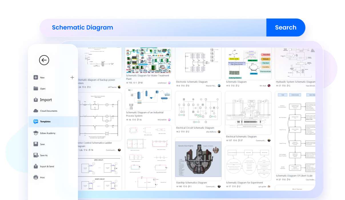
Explore vast free templates and symbols
EdrawMax offers an extensive library of free templates and symbols, covering various fields of engineering. These templates provide a quick starting point, saving time and inspiring creativity for a wide range of projects.
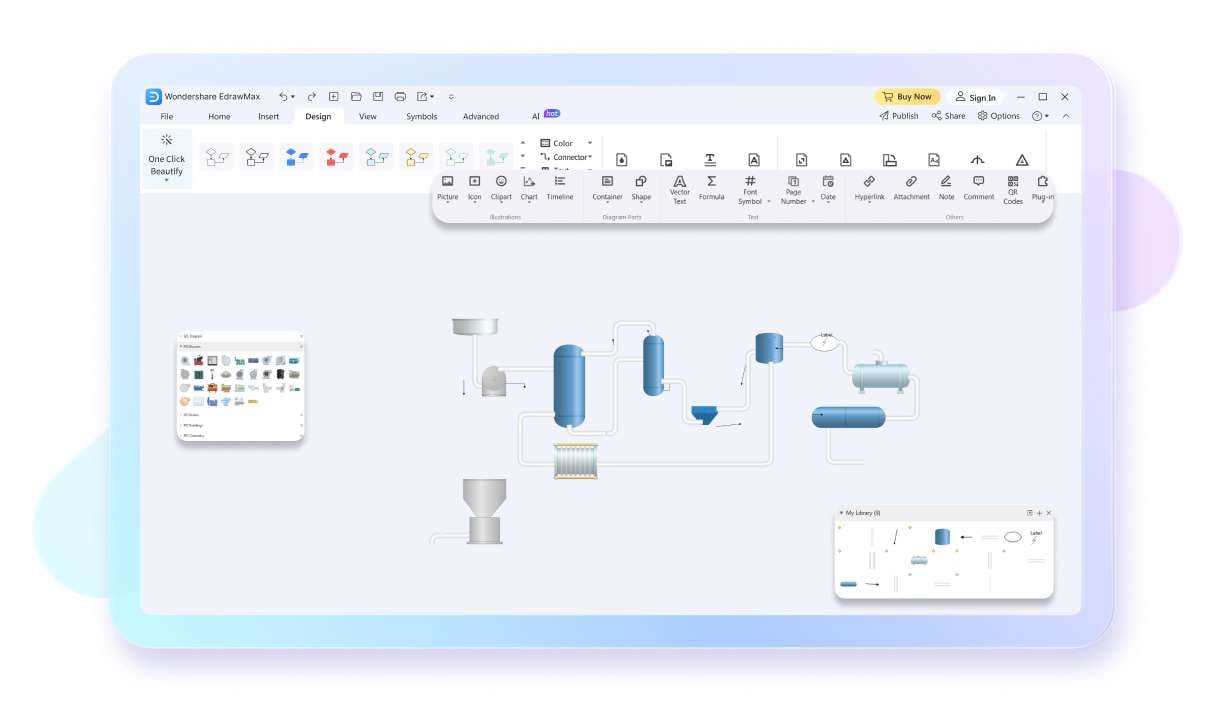
Customize easily with drag-and-drop ease
EdrawMax features a user-friendly interface with powerful customization options. Users can access a personal library for tailored assets and employ drag-and-drop functionality for easy manipulation, making complex designs straightforward and accessible.
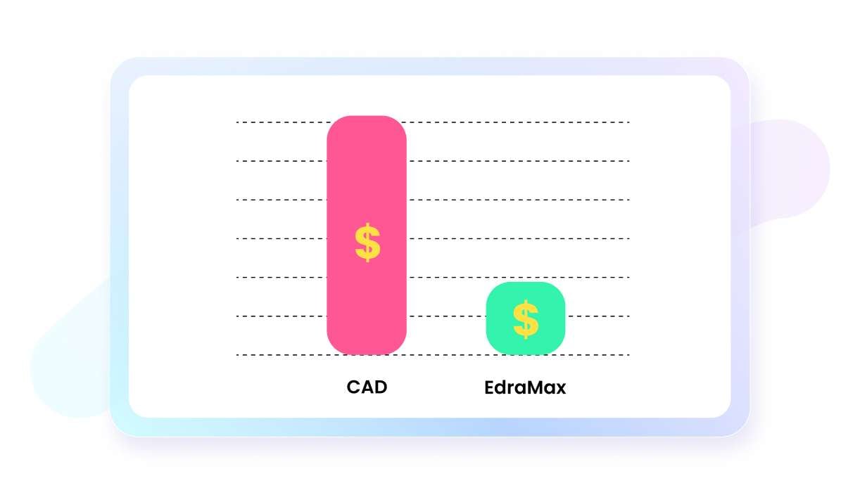
Enjoy affordable diagramming solutions
EdrawMax stands out with its competitive pricing, offering a range of affordable plans. This pricing structure makes professional diagramming tools accessible to individuals and businesses of all sizes without compromising on features or quality.
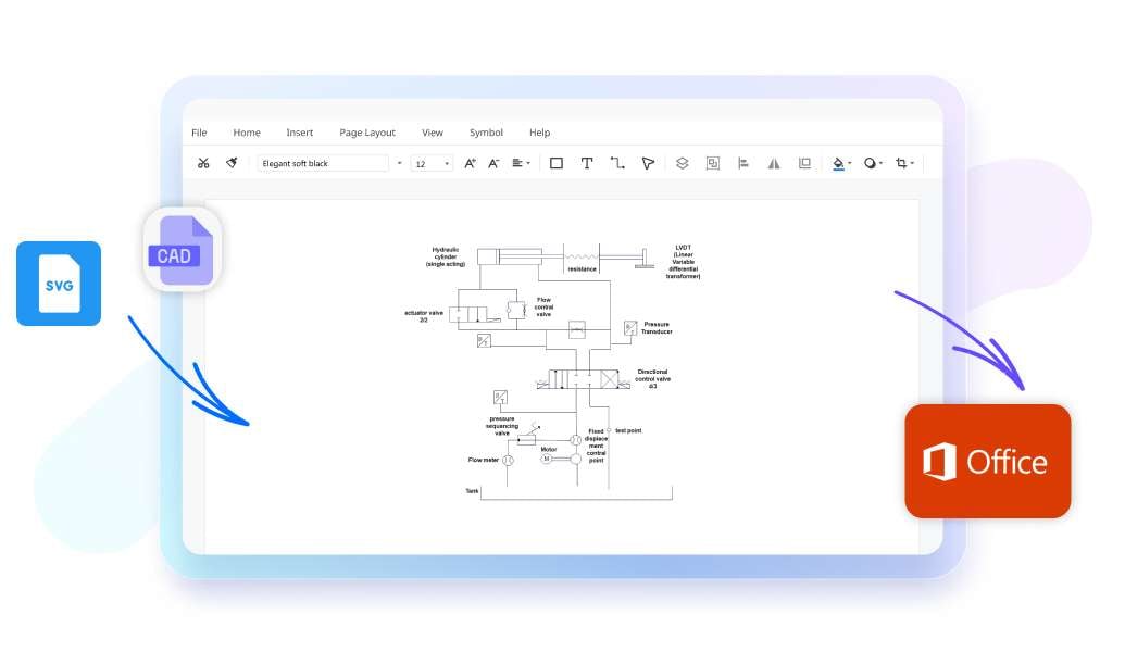
Seamlessly integrate with leading apps
The software seamlessly integrates with popular applications such as CAD, Visio, and Microsoft Office. This compatibility enhances workflow efficiency by allowing users to import, edit, and export diagrams across different platforms effortlessly.
present floor plan with EdrawMax
Utilize across multiple platforms effortlessly
EdrawMax is designed for versatility, supporting various operating systems, including Windows, macOS, and Linux. This cross-platform support ensures a consistent experience for users, whether they are working on a PC, Mac, or a Linux-based system.

Schematic diagram maker for everyone

banner
Electrical Engineers
Create circuit diagrams, schematics, and wiring layouts for electrical systems and equipment installations.
banner
Mechanical Engineers
Use for process block diagrams, mechanical system designs, and equipment schematics in manufacturing and engineering projects.
banner
Civil Engineers
Design and communicate building layouts, ensuring efficient use of space and accurate construction plans.

Why do users choose EdrawMax?

banner
Precise in design
EdrawMax offers various high-precision features like auto-aligning for accurate designs, ensuring both visual appeal and functional efficiency in various spaces.
banner
Intuitive and beginner-friendly
EdrawMax's user-friendly interface and intuitive design tools make diagramming accessible to all, from experienced architects to first-time users, fostering creativity and effortlessly turning visions into reality.
banner
Affordable and cost-effective
EdrawMax's free version and flexible paid plans make it a cost-effective choice, allowing efficient resource allocation and empowering users to create intricate schematic diagrams without high cost.
banner
Efficient and time-saving
EdrawMax streamlines diagramming with robust features and vast libraries of templates and symbols, saving time for engineers to bring ideas to life promptly.
What is
a schematic diagram

A schematic diagram is an abstract, graphical representation of a system, crucial for understanding the components and relationships within it. Unlike physical layout diagrams, schematics emphasize the flow and connections between different elements, using standardized symbols to denote various components. This simplification aids in comprehending complex systems by focusing on their operational logic rather than their physical arrangement.

In many technical fields, such as electronics, hydraulics, and architecture, schematic diagrams play an integral role. In electronics, for example, they depict how components like resistors, capacitors, and transistors are interconnected in a circuit. The symbols are universally recognized within the field, ensuring that anyone with the necessary knowledge can understand and interpret the diagram, irrespective of language barriers.

Schematic diagrams are particularly valuable in troubleshooting and problem-solving. They help identify functional connections and potential fault points in a system. By studying a schematic, technicians and engineers can diagnose issues and understand how altering one component might affect the entire system.

Moreover, in the design and construction of new systems, schematic diagrams are indispensable. They allow engineers to plan the layout and interactions of components before physical construction, ensuring efficiency and avoiding costly errors. The use of schematic diagrams spans across various stages of project development, from conceptualization to maintenance, underscoring their importance in both creation and ongoing management of systems.

Why use
a schematic diagram?

A schematic diagram is employed primarily for its ability to simplify and clarify complex systems. By distilling intricate structures into standardized symbols and connections, it renders the understanding of multifaceted networks, electronic circuits, or mechanical systems more accessible. This simplification is crucial in various fields like engineering, architecture, and electronics, where the clear representation of how components interact is more important than their physical arrangement or scale.

In design and troubleshooting, schematic diagrams are invaluable. They provide a high-level overview of how a system functions, allowing designers and engineers to conceptualize and implement solutions effectively. For instance, in electronic circuit design, a schematic is essential for understanding the connectivity and operation of the circuit before any physical implementation occurs. This preemptive visualization helps in avoiding costly design errors and inefficiencies.

For educational and communication purposes, schematic diagrams are incredibly effective. They serve as a universal language in technical fields, transcending linguistic barriers. Their standardized symbols and formats allow for easy sharing and comprehension of ideas and concepts across diverse teams and disciplines, facilitating collaboration and learning.

Finally, in maintenance and documentation, these diagrams play a key role. They assist technicians in identifying components and understanding systems without the need for detailed physical descriptions. This aspect is particularly vital in industries where safety and precision are paramount, such as aerospace and chemical processing. The use of schematic diagrams ensures that complex systems are maintained accurately and efficiently, underlining their significance across various sectors.

Tips for
using schematic
diagrams

Schematic diagrams are essential tools in various technical fields, and using them effectively requires a keen understanding of their purpose and design. These diagrams represent complex systems using standardized symbols, which allows for a clear depiction of how different components are connected and interact. The first step in utilizing schematics effectively is to familiarize oneself with these symbols, which vary across different industries like electrical, hydraulic, or architectural engineering.

When interpreting a schematic diagram, it's important to concentrate on the connections between elements rather than their physical placement. Schematics are designed to communicate the functionality and relationship of parts within a system, not to represent their actual spatial arrangement. Understanding this fundamental aspect helps in correctly analyzing and applying the information presented in the diagram.

Maintaining accuracy and consistency is crucial when working with schematic diagrams. Regular updates and revisions should be made to reflect any changes in the system. This ensures that the schematic remains a reliable and up-to-date representation of the system. Additionally, employing color coding and clear labeling can significantly enhance readability and comprehension, aiding in quicker and more efficient interpretation.

Finally, integrating schematic diagrams with supporting documentation and real-world applications enhances understanding. Practicing with actual examples, referring to additional materials like parts lists or descriptions, and not hesitating to seek clarification when needed, are all practices that contribute to more effective use of schematics. These methods collectively improve one’s ability to interpret and apply the information from schematic diagrams accurately in various professional contexts.

How to
make a schematic diagram?

Planning and research: Begin by thoroughly understanding the system or concept you intend to represent. Gather all necessary information, data, and requirements. This stage involves determining the purpose of the schematic and identifying its key components and how they interact. Planning helps in ensuring that the schematic will be accurate and comprehensive.

Selecting a tool: Choose an appropriate diagramming tool that suits your needs. There are various software options available, such as EdrawMax, AutoCAD, or even simple tools like Microsoft Visio. These tools offer a range of symbols and templates that can be used to accurately depict different components and processes.

Designing the diagram: Start by laying out the primary elements of your system. Use standard symbols and notation relevant to your field to ensure clarity and consistency. Connect these elements using lines to represent relationships or flows. Pay attention to the layout, ensuring that the diagram is not cluttered and is easy to follow.

Review and refine: Once the initial draft is complete, review the diagram for accuracy and clarity. It’s important to ensure that the schematic is not only correct but also understandable to its intended audience. Seek feedback from peers or experts in your field, and make necessary adjustments. This iterative process will help in refining the schematic to its final, polished form.

How to
read schematic diagrams?

Learn standard symbols: The first step in reading schematic diagrams is familiarizing yourself with the standard symbols used to represent various components. This includes basic elements like resistors, capacitors, diodes, and more complex components such as transistors and integrated circuits. Each symbol is standardized and universally recognized in the field of electronics, making it crucial to learn and recognize these symbols.

Understand circuit flow: Schematic diagrams are typically drawn with a flow from left to right and top to bottom. This directional flow represents the path of electrical current through the circuit. Recognizing this flow is key to understanding how different components are interconnected and how they influence each other within the circuit.

Recognize configurations and relationships: Beyond individual components, it’s important to identify common configurations or sub-circuits, such as series and parallel connections, and how they impact the overall circuit function. This involves understanding the relationship between components, such as which components are in series or parallel to each other, and how this affects the circuit's behavior.

Applying electrical theory: A basic understanding of electrical theory, including concepts like Ohm's Law, Kirchhoff's Laws, and the principles of current and voltage, is essential. This theoretical knowledge supports the practical interpretation of schematic diagrams, allowing for a deeper understanding of circuit functionality and aiding in troubleshooting and design modifications. With practice and experience, reading and interpreting schematic diagrams becomes an intuitive process for anyone in the field.

  • 1.
    What is a schematic
    diagram?
  • 2.
    Why use a schematic
    diagram?
  • 3.
    Tips for using schematic
    diagrams
  • 4.
    How to make a schematic
    diagram
  • 5.
    How to read schematic
    diagrams

Schematic diagram templates from EdrawMax

Wiring Diagram
Genogram
Piping Line Diagram
Wiring Diagram
Circuit Diagram
Schemetic Diagram for Chemistry

What our users say

Tina Johnson, consultant
I've tried several diagramming tools, but EdrawMax stands out for its schematic diagram features. It's intuitive, and the templates save me a ton of time. It's my go-to tool for presentation.
Michael Blair, programmer
EdrawMax is a game-changer for creating schematic diagrams. As a software engineer, I rely on it daily for designing software architecture. The vast symbol library and customization options make it a breeze to use. Highly recommended!.
Aaron Williams, electrical engineer
EdrawMax has simplified my workflow as an electrical engineer. Creating circuit diagrams and wiring layouts is effortless with EdrawMax's drag-and-drop interface. The export options are versatile, allowing me to share diagrams easily. Great tool.

FAQs about schematic diagram makers

  • EdrawMax offers both subscription-based and perpetual pricing plans. Customers also have the option to purchase EdrawMax bundled with other products for additional discounts. For more detailed information, it's recommended to visit the pricing page.
  • EdrawMax offers special discounts to students on subscription-based plans, available upon providing specific information to verify student status. For detailed information about eligibility and how to apply, please visit our pricing page for education.
  • Yes, EdrawMax supports collaboration, allowing multiple users save diagrams on the cloud and work on the same diagrams, which is especially useful for team projects. You can share your diagrams through a link.
  • EdrawMax is acclaimed for its beginner-friendly nature, featuring an MS Office-like intuitive interface that eases the learning process. Its simplicity is a key factor in user preference, as revealed by user surveys. For further assistance and resources, please read our user guides to learn how to use the software.
  • EdrawMax supports a wide range of export formats, allowing for versatile use of diagrams. Key formats include VSDX, PDF, Word, Excel, PowerPoint, and various image formats like JPG, PNG, SVG, and more, ensuring compatibility with different platforms and uses.
  • Indeed, creating a schematic diagram online is feasible with tools like EdrawMax. As a renowned online diagramming software, EdrawMax provides an extensive collection of templates and specialized features for creation of schematic diagrams. It enables users to effortlessly drag and drop pre-made shapes, customize dimensions, and incorporate various elements such as furniture, making it simple to design detailed and professional schematic diagrams.