- All templates
- Composite structure diagram templates
- Composite diagram atm
About this composite diagram for ATM
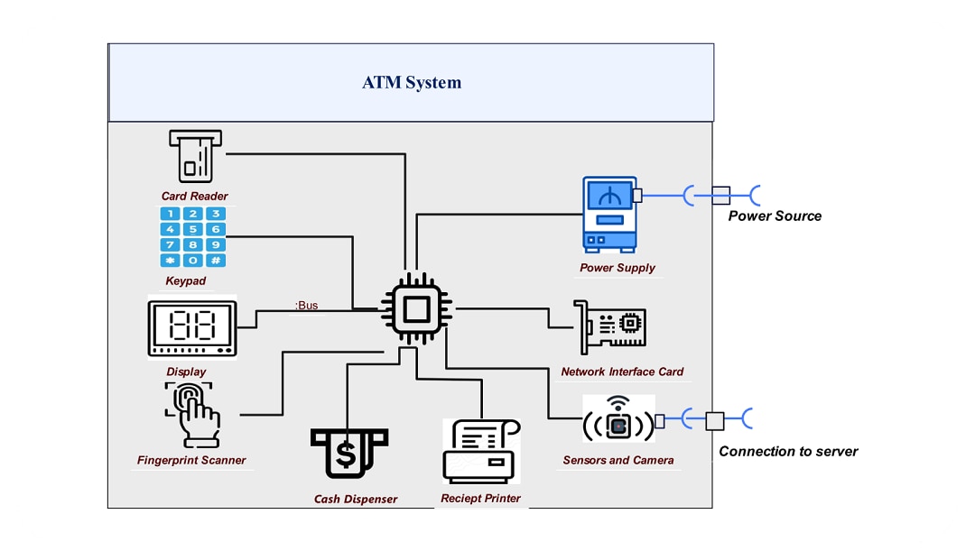
The UML composite diagram of the ATM system details its parts. It shows how they connect to provide seamless automated banking solutions. This diagram shows how hardware and software work together. It ensures that services are rendered to the consumer safely and quickly.
The main elements are the user interface, card reader, keypad, display screen, transaction processor, network interface, cash dispenser, receipt printer, and security modules. Each is vital for the system to work.
User interaction takes place through the user interface, which covers the display screen and keypad. The screen shows messages that process the user's transaction. It gives instructions and responses at all stages of the transaction. The keypad lets the user enter their PIN and select a transaction type. These inputs are essential for commencing and executing other banking processes.
The card reader accepts or reads a user’s bank card. It retrieves data from the card's magnetic strip or microchip. It uses this to verify the user and look up bank records. This is to ensure that only the right individuals access their accounts. It aims to protect against any illicit activities during financial dealings.
Upon reading the card, the user is verified. Then, the transaction processor runs the logic and executes the transactions. This particular component works along with the network interface. The transaction processor checks account balances. It withdraws or deposits cash and alters account details, all in real time to maintain order in the banking system.
The cash dispenser is a key hardware part. It provides cash to the user. It only dispenses the requested amount. It has features to prevent bank theft.
There are security modules integrated into the entire ATM system to prevent access and eliminate fraud. These are transmission encryption, user activity cameras, and intrusion and behavior detection systems. Also, the power supply keeps the ATM running.
The maintenance interface lets bank staff make routine checks and updates, and troubleshoot as needed. This component aims to keep the ATM in top condition. It does this in the least time possible to satisfy clients. Ready interventions are vital for hardware failures and software updates. They help the ATM handle prolonged use.
The UML composite diagram for the ATM system shows how the components work together. The ATM system composite diagram elaborates on each part and circles their relationships. In this way, the diagram explains how ATMs can provide secure, quick, and responsive banking transactions to clients.
Related templates
Get started with EdrawMax today
Create 210 types of diagrams online for free.
Draw a diagram free Draw a diagram free Draw a diagram free Draw a diagram free Draw a diagram free


