- All templates
- Composite structure diagram templates
- Composite diagram vehicle system
About this composite diagram for vehicle system
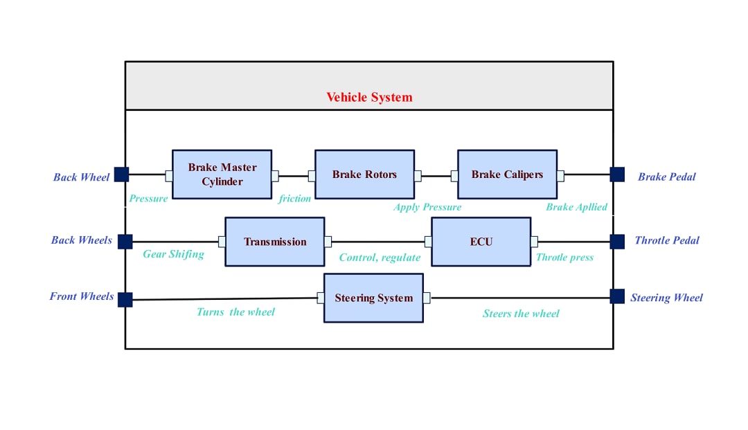
The UML composite diagram for a vehicle system shows its structure and operation. It also shows its main subsystems and their elements. It shows how various mechanical and electronic parts work together to run the vehicle efficiently.
The composite diagram mainly shows the brake, transmission, and steering systems. It also shows the ECU. It relates them to user input via the brake pedal, throttle pedal, and steering wheel.
The first component is a brake master cylinder. It converts the driver's force on the brake pedal into hydraulic pressure. This pressure so generated is then sent to the brake rotors, which then causes the vehicle to slow or stop due to friction. The brake calipers also apply this pressure onto the brake rotors to help with the braking and safety purposes. This hydraulic system operates harmoniously to ensure effective braking is achieved especially on the rear wheels.
The transmission system is positioned as the link between the engine and wheels, controlling the shifting of gears to distribute power and torque most effectively. It helps to accelerate and decelerate the motion in a controlled manner to the motion of the back wheels.
This element works with an electronic control unit (ECU). The ECU manages functions in vehicles, including the throttle, gears, and overall performance. The ECU converts the driver's throttle pedal input. It regulates the engine's power output. This allows for very responsive driving.
The steering system connects the handgrip to the front wheel axles for direction. It does this within the steering hemisphere. This system ensures that the twisting motion of the steering wheel is correspondingly matched by the motion of the wheels allowing the vehicle to turn without difficulty.
Each subsystem in this UML diagram for the vehicle system has a distinct function. It contributes to the vehicle's overall operation. The dynamics of braking, power control, and steering systems make the vehicle safe, efficient, and operable with ease. Further, this UML diagram helps in understanding the basic principles of combining mechanical and electronic systems to achieve the desired vehicle operation.
Related templates
Get started with EdrawMax today
Create 210 types of diagrams online for free.
Draw a diagram free Draw a diagram free Draw a diagram free Draw a diagram free Draw a diagram free


