- Templates
- Circuit diagram templates
- Servo motor circuit diagram
About this template
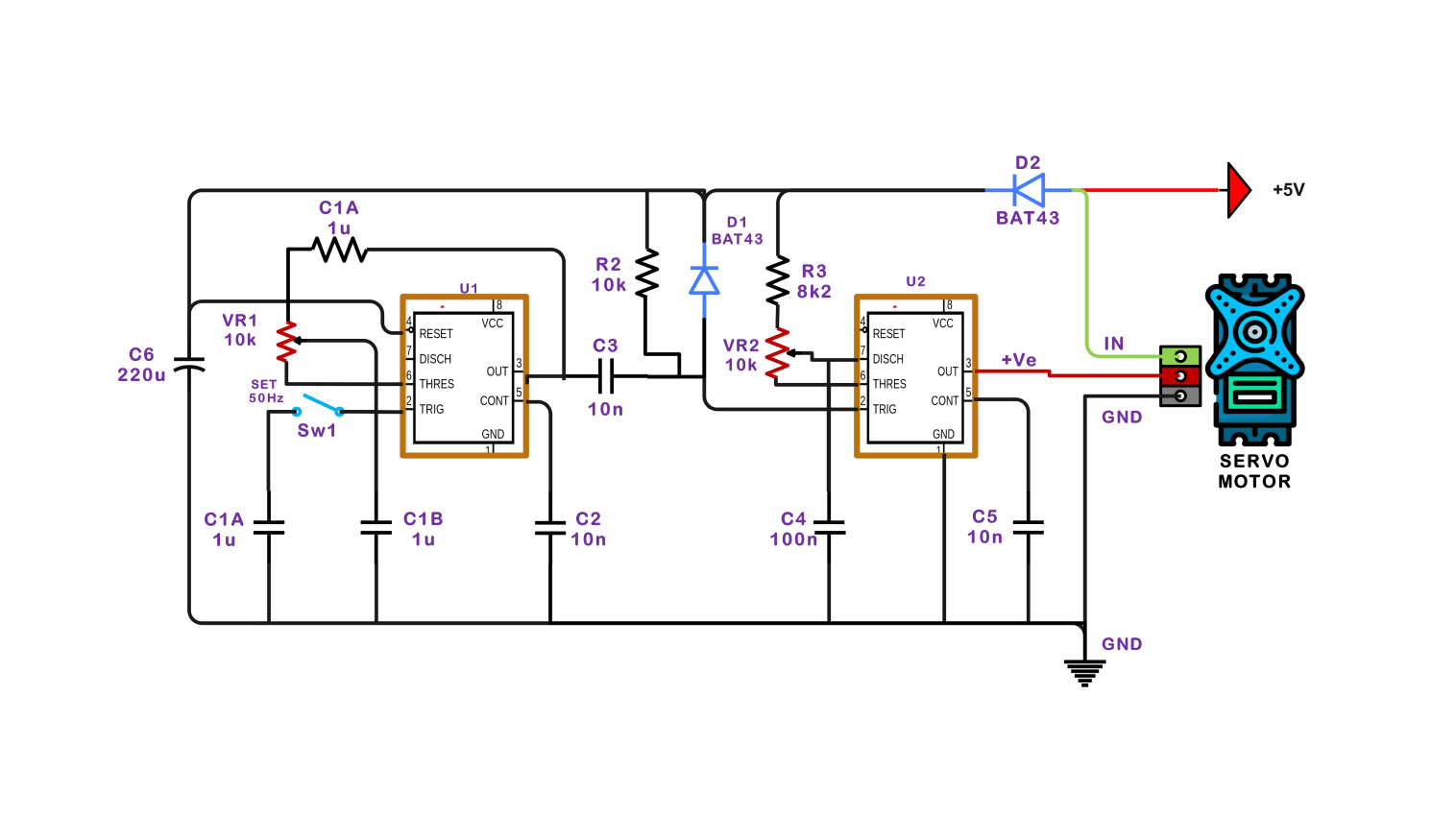
The described control circuit for the servo motor includes two NE555 timer ICs for creating a square wave that is a pulse-width signal to enact the desired servo speed and position. NE555 IC is configured in a stable mode.
For this setup, it generates a square wave that regulates the speed of a servo motor according to its frequency. With the input of varying resistor and capacitor values, a square wave with a frequency that would make the motor speed change is generated.
The second NE555 IC functions as a stable type which drives the position of the servo motor. The IC generates a pulse width that varies proportionally to the potentiometer input. Once you set the desired angle by changing the position of the potentiometer, the servo motor will start to move.
How to use the template
Click on Edit it online to open this circuit diagram of servo motor. Once the template has opened, look for the Libraries panel on the left side. There you can find all the electrical components that you might want to add in. Drag and drop the needed symbols onto your canvas.
Under Electrical Engineering, expand the Basic Electrical category. You can swap components, adjust values, and even add labels to tailor the circuit. You can also change line styles, colors, and text fonts for better clarity.
Now click File > Export and choose your preferred format (e.g., image file, PDF, SVG) to share and export to the diagram.
Benefits of the template in electrical design
Using servo motor circuit diagrams offers numerous advantages. Firstly, they provide a clear and concise representation of how components like motors, controllers, and sensors are interconnected within the system. This visual aid enhances understanding, making it easier to identify and troubleshoot issues when they arise.
Secondly, circuit diagrams serve as valuable documentation for design and modification. Engineers and hobbyists can use them as a blueprint for assembling and integrating servo motors into larger systems, ensuring proper connections and compliance with safety standards.
Circuit diagrams play a crucial role in the development, maintenance, and educational aspects of servo motor applications, offering a structured approach to building and understanding these systems.
FAQs about circuit diagrams
-
What makes a servo motor unique?
Unique features of servo motors:
- Precise Positioning:
- Closed-Loop Control System:
The difference between regular motors and servo motors is not in the spinning of these motors but in the provision of precision angular control. The rotary motion feedback mechanism is built into the main body and consequently, the shaft position is continuously monitored.
As in the feedback mechanism and control circuit, the feedback loop forms the closed control system.
-
Does a servo draw current when not moving?
The servo motor is considered a frost current device because it draws some even when it has been stilling. The continuous drain of current is made to feed information regarding the motor's position and its state of readiness so that movements initiated by the control signals can be quick and accurate always.
-
Is servo AC or DC?
Servo motors can be DC motors. Their operation can be similarly rationed by a DC power source. The accurate positioning is achieved with a pulse width modulation (PWM) signal. However, the only power to the motor is direct current (DC).
-
Is the servo motor synchronous?
Servo motors are not inherently synchronous motors. Synchronous motors maintain a constant speed relative to the power line frequency (50Hz or 60Hz). Servo motors, on the other hand, can move at various speeds and hold specific positions as needed, independent of the power line frequency.
Related Templates
Get started with EdrawMax today
Create 210 types of diagrams online for free.
Free Download Free Download Draw a diagram free Draw a diagram free Draw a diagram free