Relay wiring diagram
This free template acts as a wiring guide for using relays in electronics.
- Templates
- wiring diagram templates
- Relay wiring diagram
About this template
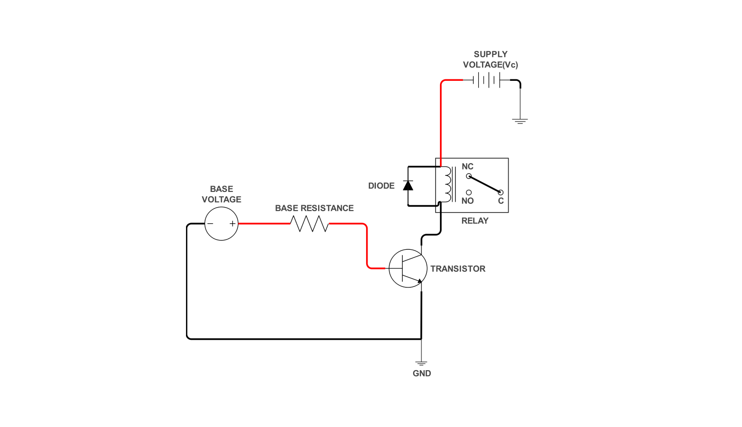
A relay driver circuit is a link that connects low-power level control measures to high-powered devices. It provides a simple control of relays for smaller processors such as microcontrollers or Arduino. This very small existing part, actually ensures that the operation will not get into potential hazards.
A transistor is similar to a switch that becomes active when a low-level signal directs it. Now this signal activates the transistor which makes the relay coil, a high-power electromagnet. While the control signal is active, the transistor stays on and the relay coil current continues.
With the control signal termination, the transistor malfunctions and generates pulses of voltage that might be sufficient to destroy some electronic parts near the transistor. The diode analyzes these spikes and makes a good interception, safeguarding the system big time and allowing the transistors to function smoothly.
How to use the template
Click on Use this template on the template to open it.
Once the template has opened, look for the Libraries panel on the left side. There you can find all the electrical components that you might want to add in. Drag and drop the needed symbols onto your canvas.
Under Electrical Engineering, expand the Basic Electrical category. You can swap components, adjust values, and even add labels to tailor the circuit. You can also change line styles, colors, and text fonts for better clarity.
Click File > Export and choose your preferred format (e.g., image file, PDF, SVG) to share your diagram. Finally, click Export to finalize your export process.
Benefits of the template in electrical design
Here's how it can help:
- Visualization and planning:
- Plan the physical layout of the circuit.
- It helps user to identify potential issues early on, like ensuring the chosen relay can handle the current of the device it controls.
- Understanding circuit functionality:
- This will help the user to control signal from the switch triggers the relay.
- Give knowledge about how relay activates the load (device being controlled).
- Troubleshooting:
- If a built circuit isn't working as expected, the diagram serves as a reference for troubleshooting.
- Designers can trace the connections to isolate where the problem might lie in the circuit.
The diagram acts as a blueprint showing how various electrical components (relay, resistors, switch, power supply) are connected and interact. This allows electrical designers to:
By following the connections and understanding the role of each component, designers can understand how the circuit works:
FAQs about wiring diagrams
-
Does a relay draw power?
Yes, relays do draw power, but it depends on two parts:
- Control Circuit
- Relay Coil
The control circuit uses a low-power signal (from a microcontroller or switch) to activate the relay coil. It consumes minimal power. The relay coil uses a stronger current to generate a magnetic field. The relay coil draws more current than the control circuit.
-
How many connections does a relay have?
The number of connections on a relay depends on the specific type, but most common relays have:
- Coil terminals:
- Contact terminals
These connect to the control circuit and allow current to flow through the coil, activating the relay.
These are physically separate terminals that switch when the relay is activated. There can be multiple sets depending on the relay type (e.g. Normally Open (NO), Normally Closed (NC), or combinations of both).
-
Does a relay need AC or DC?
Relays can be designed for either AC or DC operation. The type of relay you need depends on the power source of your control circuit.
- DC relays:
- AC relays:
These are more common and are often used with micro-controllers or Arduino's that operate on DC power.
These are used in circuits with AC power sources and might be required for controlling high-power AC devices.
Related templates


Get started with EdrawMax today
Create 210 types of diagrams online for free.
Free Download Free Download Draw a diagram free Draw a diagram free Draw a diagram free