Distillation column P&ID diagram
Craft your distillation process with a free, intuitive tool.
- Templates
- P&ID diagram templates
- Distillation column P&ID diagram
About this template
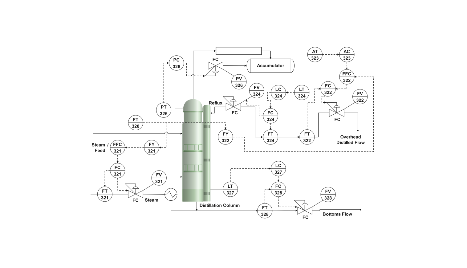
This piping and instrumentation diagram describes the process flow of a typical fractional distillation column. Fractional distillation is a process that breaks down a mixture of two or more volatile liquids concerning their boiling points. It relies on the difference in volatility (boiling point tendency) of the components in the mix.
The vertical column is the separation tower, also called the distillation column. Feed is introduced into the distillation column as the raw material at a specified point. At the bottom of the separating chamber, a reboiler exists. This reboiler heats the liquid and vaporizes the incoming feed.
These vapors travel upwards through the column. As the vapor rises above, it encounters the condenser, which is located at the top of the separating chamber. The condenser acts as a cooler, changing the vapor state to liquid. The crucial element of the separating chamber is the temperature gradient.
It is hottest at the bottom and gradually cools as you move towards the condenser. The most volatile component condenses first due to cooler temperatures at the top. The condensed liquid is the purified product with the lowest boiling point, which is collected and called distillate.
The distillation column also contains internal structures like trays and other packing material. As the vapor rises toward the top, it comes in contact with the plates, condensing it and partially re-evaporating it based on its boiling point.
How to use the template
Click on Use this template Customize the template according to your requirements, and drag symbols from the library to add the necessary equipment or instruments to your process by searching for them in the left pane.
Style and edit lines, shapes, and text to clarify your PID diagram visually. Adjust the pipe pathways to match your specific distillation process. Common elements and shapes can also be saved in the library.
After you are finished, export the diagram in various formats. Your options include SVG, PPTX, PDF, or JPG.
Why P&ID diagram for the distillation column
A P&ID diagram is a blueprint of any process flow or manufacturing setup. It involves all the design constraints, arranging the pipes and equipment, and all the instruments involved. This allows the engineers to determine the physical layout, sizing of equipment, and equipment placement.
The P&ID diagram also helps as a reference for process operators. It provides a clear picture of the flow of materials, control loops, and valve placement. The operator can adjust the parameters of the instruments by using these diagrams.
The P&ID diagram of a distillation column is a vital facilitating agent that provides insights and coordination in the domains of design, operation, maintenance, and communication. It assures the manufacturing industry of effective and safe management of all the distillation process systems.
FAQs about distillation column P&ID
-
What is the principle of the distillation column?
A distillation column, or fractional distillation column, separates two or more mixed liquids based on their boiling points. It consists of a tower-like structure that achieves this process by utilizing different phenomena like heating, vaporizing, condensing, and temperature control.
-
What is a P&ID diagram of a process?
A P&ID diagram is a detailed schematic diagram used in process industries to map the industry's process flows. It visually represents the flow of fluid and material in a system and focuses on piping (electrical and mechanical) and the instruments used to control the process.
-
How to design a distillation column?
The design of a distillation column involves many parameters, such as product composition, product flow rates, heat inputs, number of trays, column diameter, and column height. This template allows for customization of any design as required.
Related Templates

Get started with EdrawMax today
Create 210 types of diagrams online for free.
Free Download Free Download Draw a diagram free Draw a diagram free Draw a diagram free