PID water processing
Build your wastewater treatment plant for free with an intuitive design.

- Templates
- P&ID diagram templates
- PID water processing
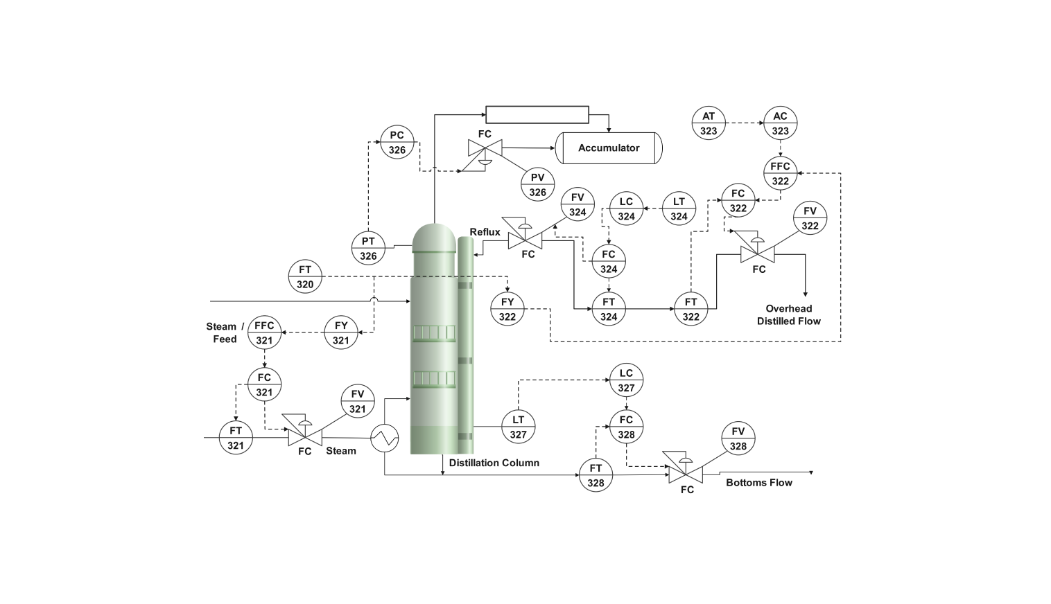
About the PID water processing diagram
This piping and instrumentation diagram describes the process flow of a wastewater treatment plant. Wastewater is treated to remove containments and make it functional to reuse or discharge into the environment.
The wastewater treatment plant processes the impure water through several stages. The polluted water is inserted in a grit chamber, removing large particles.
The water is then fed to the primary sedimentation tank, which settles the heavy solid particles and removes them from the water. The water is then fed to the bio-treatment chamber for further processing.
At this stage, the biological processes remove organic matter in the water. The water is then fed into the second sedimentation tank, allowing any remaining solid particles to settle down and the impurities to be removed from the water again.
The tertiary tank removes any dissolved pollutants at this step, and chlorine is added to the water to kill bacteria. After chlorination, the treated water is discharged for further use.
How to use the template
Click on Use this template. Customize and modify the template according to your needs, and drag symbols from the library to include the tools or equipment you need in your workflow. The left-hand pane allows you to search for these symbols.
To make your PID diagram more transparent, style and modify the lines, curves, and text. Modify the pipe routes to correspond with your distillation procedure. You can also store common shapes and elements in the library for later use.
After you are finished, export the diagram in various formats. Your options include SVG, PPTX, PDF, or JPG.
Why PID Water Processing Plant?
Adopting a Process Instrumentation Diagram (PID) in a water processing plant gives the whole water treatment process a clear and complete visualization of the entire plant operation, thus making the operation safe and efficient.
The diagram highlights the principal elements of the system, such as flow rates, pressure, and temperature, which allow the operators to control and monitor the system. Thus, performance and the risk of accidents or malfunctions are decreased.
The diagram shows how different components are linked and the effects of changes within the system. The operators can see how everything is interconnected and do their jobs more effectively.
FAQs about the PID water processing diagram
-
What is PID in water treatment?
PID stands for proportional, integral, and derivative control in water treatment. It automatically controls the parameters that vary in a treatment process. PID controllers work in a closed loop that constantly monitors the tank's water level and adjusts it using a pump.
-
How many steps are included in water treatment?
The main steps included in water treatment are screening and pumping, grit removal, primary sedimentation, biological treatment, secondary sedimentation, and disinfection. Some plants also include tertiary treatment for additional filtration and removal of impurities.
-
What is the PID controller operating principle?
A proportional-integral-derivative controller, or PID controller, is frequently used in industrial systems to regulate flow rates, temperature, pressure, and speed and to control other process parameters. It continuously observes the discrepancy between the measured value and the intended setpoint.
Related Templates
Get started with EdrawMax today
Create 210 types of diagrams online for free.
Free Download Free Download Draw a diagram free Draw a diagram free Draw a diagram free