Heat exchanger P&ID diagram
Design your custom heat exchange system, add all the necessary components for free!
- Templates
- P&ID diagram templates
- Heat exchanger P&ID diagram
About the heat exchanger P&ID diagram
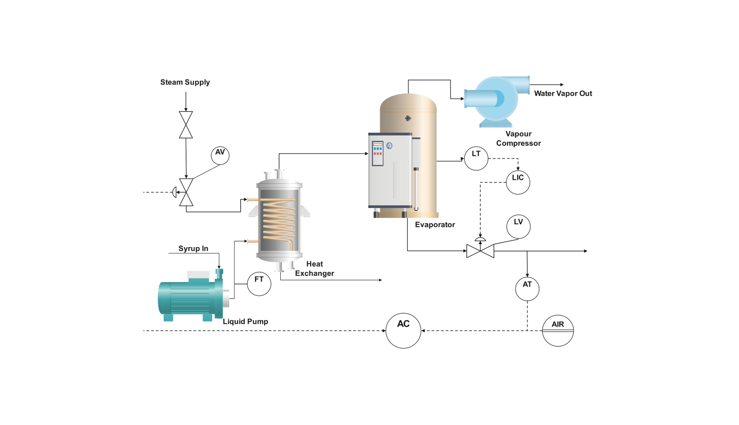
This diagram describes the process flow of a steam heat exchanger, which concentrates maple syrup and creates a thicker syrup. The heat exchanger transfers heat from hot fluid (steam) to cold fluid (maple syrup) without mixing fluids.
The heat exchanger has two inlets and exits. Maple syrup and steam are used in one inlet and exit, respectively. The evaporator is a chamber that uses heat from the heat exchanger to vaporize the liquid and concentrate the solution.
LIC is a level indicator controller used to monitor the liquid level on the evaporator. The liquid pump supplies the liquid for evaporation. An AT valve, an air bleed valve, allows air to exit the system.
How to use the template
Click on Use this template. Just click on the left panel to find the piece of equipment or instrument that you need for your process.
Style and edit lines, shapes, and text to make the PID diagram more apparent visually. Modify the pipe routes to fit your particular distillation process. The common elements and shapes can also be stored in the library for future use.
After you are finished, export the diagram in various formats. Your options include SVG, PPTX, PDF, or JPG.
Why P&ID diagram for heat exchanger
A P&ID (Piping and Instrumentation Diagram) for a heat exchanger illustrates the process flow clearly and shows the layout of the heat exchanger in the system. It enables the analyst to detect all the components of the heat exchanger system, which are the valves, instruments, and piping.
P&ID diagrams help people understand safety measures by showing safety valves, pressure relief valves, temperature, and pressure indicators. They also tell people what to do if equipment breaks down, give guidelines for repairing the equipment and its components, and help with maintenance and troubleshooting.
Engineers employ P&IDs efficiently in the design and alteration of heat exchanger systems. Hence, P&IDs work as a common language for engineers, technicians, and operators and support communication about the design, operation, and maintenance of heat exchanger systems.
FAQs about the heat exchanger P&ID diagram
-
What is a heat exchanger in P&ID?
A heat exchanger is an equipment used in a process flow diagram to transfer heat between two or more fluids. P&ID uses standardized symbols for heat exchangers, which allows users to recognize their function quickly in the process flow.
-
What is the heat exchanger layout?
The basic layout of a heat exchanger is the arrangement of its components. Many heat exchangers exist with different arrangements of flow paths and tube bundles, which affect the heat transfer rate, pressure drops, and costs.
-
What is the flow pattern in a heat exchanger?
The flow pattern is the direction in which hot and cold fluids move relative to each other. It determines the effective heat transfer rate. In parallel flow, both fluids flow in the same direction. In counterflow, both fluids move in opposite directions. Counterflow is considered to be the most effective means of heat transfer.
Related Templates

Get started with EdrawMax today
Create 210 types of diagrams online for free.
Free Download Free Download Draw a diagram free Draw a diagram free Draw a diagram free