- Templates
- ER diagrams templates
- ER diagram for student management
About this ER diagram for student management system
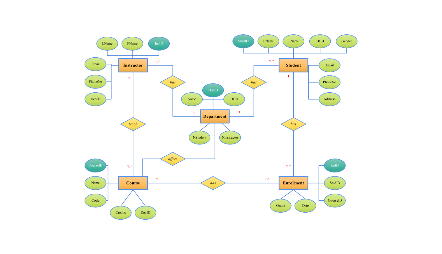
This ER diagram shows the entities and their respective relationships in a student management system. It has an instructor, a student, a department, a course, and an enrollment entity. They have specific attributes and interrelations.
An instructor has these attributes: last name, first name, email, phone no, and dep ID. Each instructor has a unique instructor ID. The "has" relationship shows the link between instructors and departments. It defines each instructor as belonging to a specific department.
Every student has a unique identity in terms of their stud ID. There exists a “has” relationship between the student and the department. This suggests that a student can be part of one department at a time.
A department includes attributes like department ID (dep ID), name, and HOD. Also, this entity tracks the number of students (n student) and instructors (n instructor) in the department. The "teach" relationship means that, within a department, instructors teach courses. Departments, on the other hand, offer various courses.
Course identifiers have five properties: course ID, name, code, credits, and department ID (dep ID). Each course has its unique identification which is derived from the course ID. By department offering courses the relationship between departments and courses is called (offers). The "teach" relationship goes further to show that instructors teach those courses.
An enrollment entity contains any information regarding student enrollment in courses. Attributes include; the enrollment ID, student ID, course ID, grade, and date. The enrollment ID uniquely identifies every enrollment record. The "has" relationship shows that several courses are enrolled by students. One course can have several enrolments by different students.
How to use this template
Click on Use this template to use it. After the template opens, customize the diagram. Drag and drop new shapes from the libraries on the left to fit your system's needs.
Edit the text. Style the boxes, lines, and text by clicking on the elements. You can save some common elements in your library. You can reuse them when creating similar diagrams.
Click the theme icon if you want to use the “one-click beautify” feature. This feature instantly changes the colors, fonts, and layout of your picture. It makes it look professional.
You can export your file in several formats for later use. Click Export to select the format (.eddx, .pdf, .png, .jpg).
Benefits of the ER diagram
For a student management system, there are great advantages that can be gained from an ER diagram in making design decisions and analyzing the system. It shows clearly all the components of the data architecture enabling one to understand better how different entities such as students, instructors, departments, courses as well as courses of study interact with each other.
By being clear on everything from the start, developers will identify issues before they happen which means that mistakes made later on when developing the application are avoided hence making it possible for them to work faster without errors.
Moreover, the ER diagram is a crucial medium of communication for different participants such as system builders, program makers, and unversed people in technology. It portrays an integral picture of data connections within the system, which ensures everyone who takes part has common knowledge of how the system is arranged and works.
FAQs about the ER diagram
-
What are the basic ER diagram symbols?
In an ER diagram, an entity is represented using a rectangular box. Each entity has associated attributes represented through ovals. All attributes are connected to their corresponding entity using a link. To show how two entities relate to each other there must be a diamond-like shape used for every such relationship on the diagram.
-
How does ER diagram help in database design for a student management system?
The ER diagram is an essential tool in database design as it helps in:
- Relationship definitions: It shows how entities such as students, instructors, and courses are related, which is important for establishing foreign key restrictions and keeping referential integrity.
- Support for logical and physical database design: The ER diagram acts as a plan or map for both the logical and physical design of the database, guiding how data should be stored, retrieved, and manipulated.
- Assuring data integrity: The ER diagram specifies primary keys and foreign keys thereby ensuring data integrity throughout the database.
-
What weak entity in an ER diagram?
A weak entity is an entity that cannot uniquely identify itself by its attributes and instead depends on a “parent” entity through a foreign key for its identification.
Related templates
Get started with EdrawMax today
Create 210 types of diagrams online for free.
Draw a diagram free Draw a diagram free Draw a diagram free Draw a diagram free Draw a diagram free


