About this Fiber Optics Network Diagram template
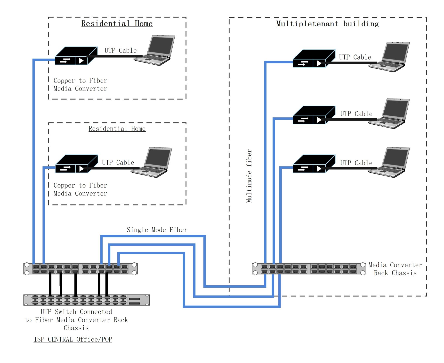
This template showcases a professional layout for Fiber-to-the-Home and Fiber-to-the-Building setups. It visualizes the connection between a central office and various end-user locations. You can use it to map out hardware requirements and cable types for network installations.
ISP Central Office and POP
The central office serves as the main hub for data distribution. It houses the core switching equipment and media converters that transform electrical signals into light pulses for long-distance transmission across the primary network.
- UTP Switch Connection
- Fiber Media Converter Rack Chassis
- Core Network Interface
- Signal Conversion Hub
Residential Home Connections
This section displays how individual homes receive high-speed internet. Single-mode fiber carries the signal to the house. Then, a dedicated media converter translates the light back into copper-based signals for local devices like laptops.
- Single Mode Fiber Input
- Copper to Fiber Media Converter
- UTP Cable Internal Wiring
- End-user Device Connectivity
Multi-tenant Building Infrastructure
Multi-unit buildings require complex distribution systems to serve many users. A central rack chassis in the building manages the incoming signal. It then uses multimode fiber to distribute data to various floors or individual office units.
- Media Converter Rack Chassis
- Multimode Fiber Distribution
- Individual Unit Converters
- High-density Laptop Connections
FAQs about this Template
-
What is the difference between single-mode and multimode fiber in this diagram?
Single-mode fiber is used for long distances between the ISP central office and the buildings. It has a small core that allows light to travel further with less signal loss. Multimode fiber appears within the multi-tenant building section. It is better for shorter distances. It handles high bandwidth over small areas effectively and is more cost-efficient for internal building layouts.
-
Why is a media converter necessary for residential fiber setups?
A media converter is essential because most consumer electronics like laptops use copper-based UTP cables. Fiber optic cables transmit data using light pulses, which these devices cannot read directly. The converter acts as a bridge. It changes the light signals from the fiber line into electrical signals that travel through standard Ethernet cables to reach your computer or router.
-
What role does the rack chassis play in the central office?
The rack chassis serves as a centralized management frame for multiple media converter modules. Instead of having many separate power bricks and loose wires, the chassis provides a neat, powered environment for the hardware. This setup allows network administrators to scale the system easily. It ensures that the ISP can support hundreds of individual fiber connections from a single organized location.