About this Use Case Diagram for Event Management System template
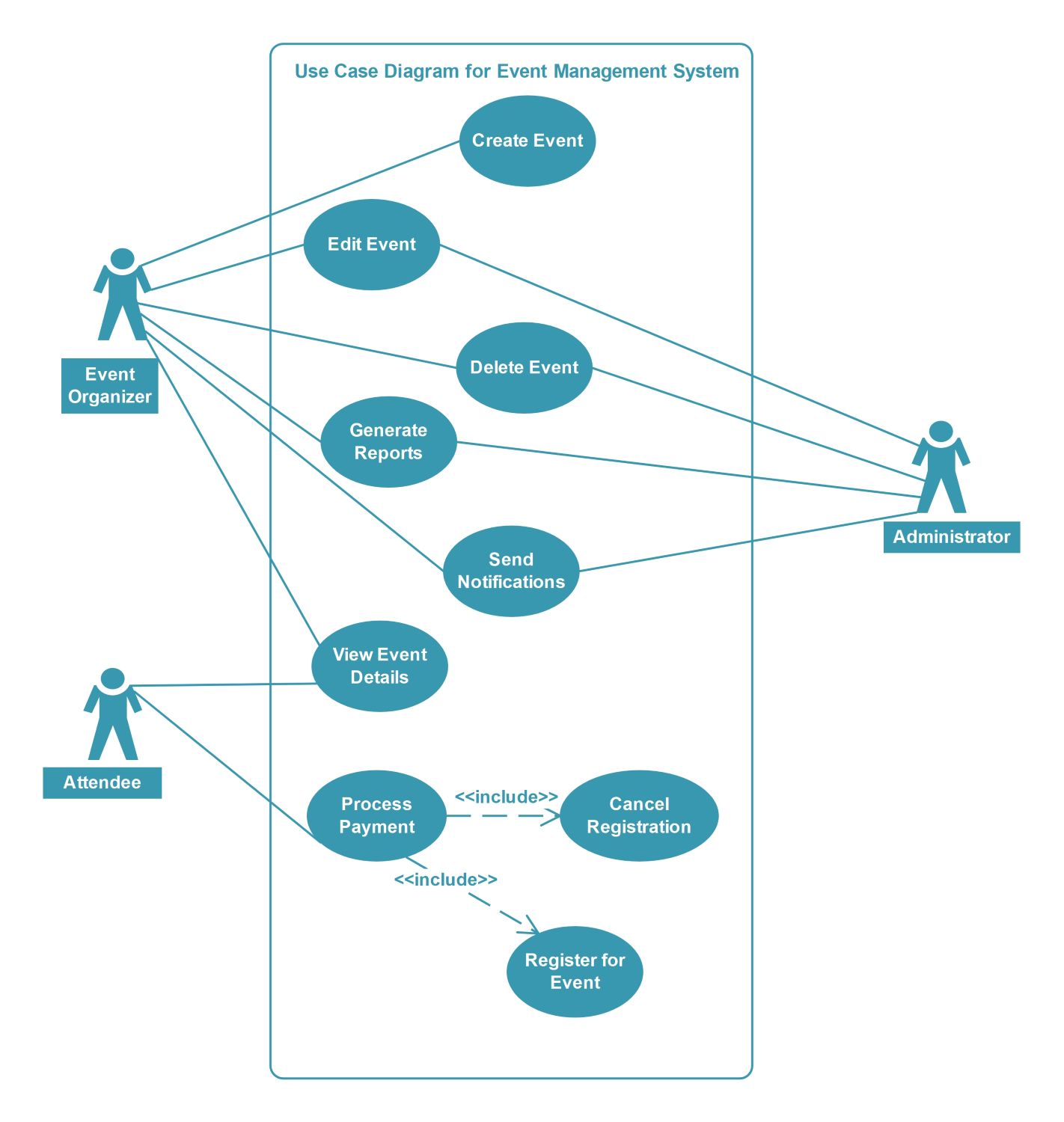
This UML template illustrates the core functional requirements of a digital event platform. It defines the boundaries of the system and identifies the primary actors who interact with the database and user interface features.
Event Organizer Role
The Event Organizer serves as the primary content creator within the system. They have the authority to manage the lifecycle of an event from initial setup to final analysis by interacting with multiple functional modules.
- Create Event
- Edit Event
- Delete Event
- Generate Reports
- View Event Details
Administrator Functions
Administrators focus on the technical oversight and high-level management of the event platform. They ensure the system remains organized and facilitate communication between different user groups through specialized backend tools and automated data handling.
- Edit Event
- Delete Event
- Generate Reports
- Send Notifications
Attendee Interactions
Attendees represent the end-users who consume event content and perform financial transactions. Their workflow is streamlined to focus on information gathering and completing the necessary steps to secure their participation in various scheduled activities.
- View Event Details
- Process Payment
System Registration Logic
The system uses specific dependencies to link financial actions with registration status. This logic ensures that payment processing is a fundamental part of the registration and cancellation workflows to maintain accurate attendance records and revenue data.
- Register for Event
- Cancel Registration
- Process Payment (includes registration and cancellation)
FAQs about this Template
-
What is the primary purpose of this Use Case Diagram?
The primary purpose of this diagram is to define the functional scope of an event management system. It identifies the relationships between external actors and internal system actions. By mapping these interactions, developers can understand user needs and build a software architecture that supports every necessary task from event creation to attendee registration.
-
Which actors are included in an event management system?
This specific system design includes three main actors: the Event Organizer, the Administrator, and the Attendee. Organizers manage the event content, while Administrators handle system-wide tasks like notifications and data reports. Attendees interact with the system to view details and pay for their spots, ensuring all user types are accounted for in the design.
-
How does the 'include' relationship function in this UML diagram?
The include relationship indicates that a specific use case is an integral part of another process. In this diagram, processing a payment is included within the registration and cancellation flows. This means the system automatically triggers payment verification whenever an attendee tries to join or leave an event, ensuring financial data stays perfectly synchronized.