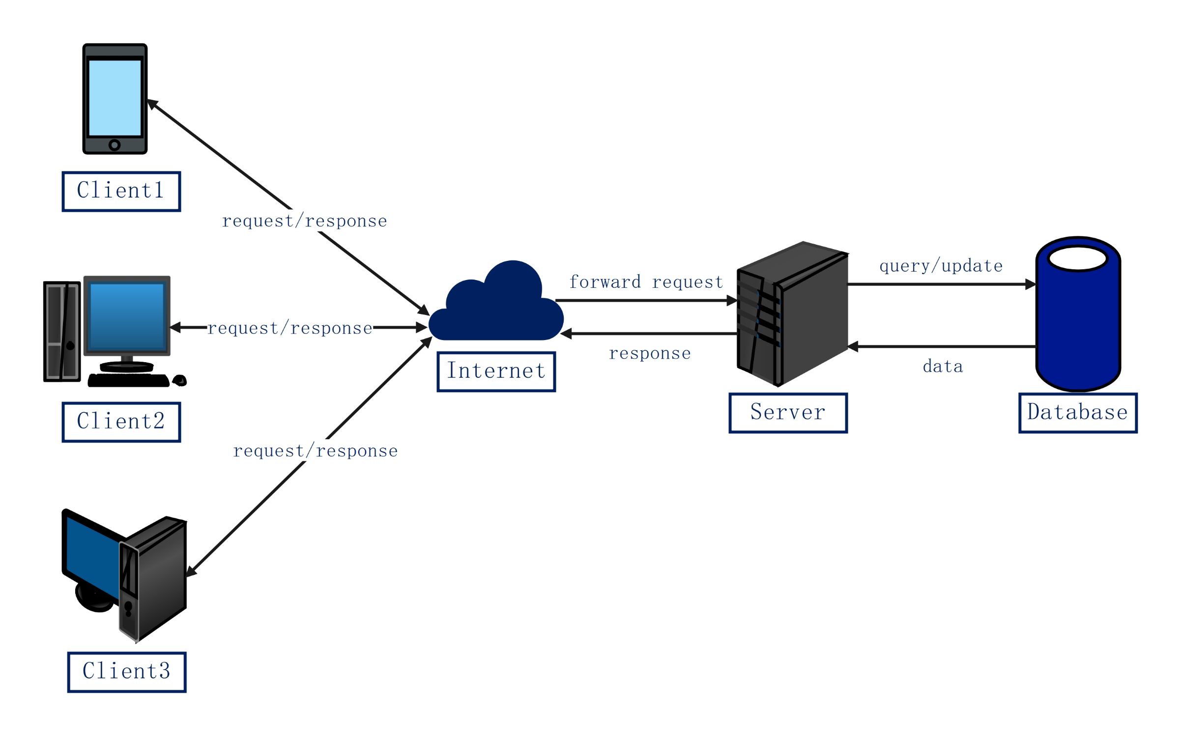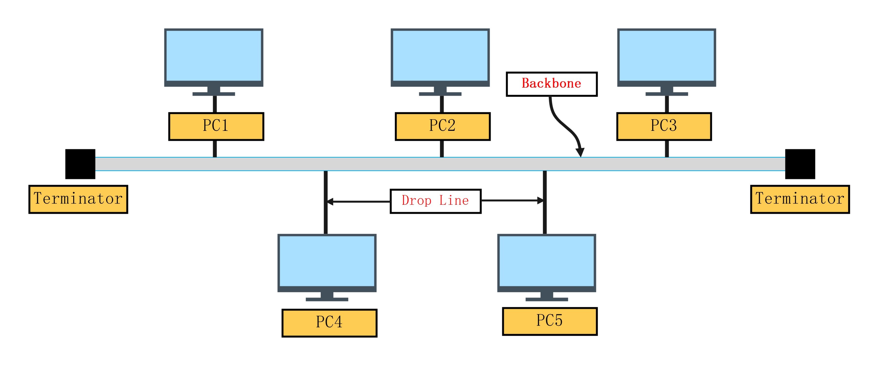
About this Bus topology network diagram template
This template provides a professional visual guide for a linear network layout. It highlights the core components needed to build a functional system. Use this to explain or plan network structures efficiently.
Network Backbone
The backbone serves as the main transmission path for all data signals within the network. It connects every device through a single central cable. This linear structure simplifies the installation process for small network environments.
- Central transmission cable
- Shared communication medium
- Primary data path
Network Terminators
Terminators are placed at both ends of the main backbone cable to absorb signals. They prevent data from reflecting back along the wire, which could cause interference. This ensures communication remains clear and error-free.
- Signal absorption points
- End of line markers
- Echo prevention
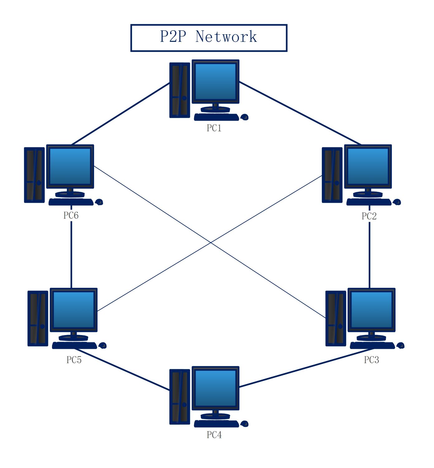
Drop Lines and Nodes
Drop lines are short cables that link individual computers to the main backbone. Each computer functions as a node on the network. This setup allows multiple devices to share information through a single primary connection.
- PC1 to PC5 devices
- Connection interface
- Individual workstation nodes
FAQs about this Template
-
How does a bus topology network function?
A bus topology network functions by transmitting data along a single central cable known as the backbone. Every device on the network is connected to this main wire using drop lines. When a device sends a message, the signal travels in both directions to reach every node. Only the intended recipient processes the data, while terminators at the ends stop the signal.
-
What are the main advantages of using a bus topology?
The main advantages include low costs and simple installation procedures. Since it requires less cabling than other topologies like star or mesh, it is very economical for small offices. It is also easy to add new devices by simply extending the backbone. This makes it a great choice for temporary setups or environments where a complex wiring system is not necessary.
-
What happens if the backbone cable fails?
If the main backbone cable fails, the entire network goes down immediately. This central point of failure is the biggest disadvantage of a bus topology. Because all devices rely on that single line for communication, a break anywhere prevents signals from reaching their destination. Troubleshooting can be difficult because a single fault affects every computer, making it less reliable for large, critical systems.