


Anyone who works with circuits needs to know electronic symbols. These symbols act as essential circuit diagram components, improving communication among engineers and electricians. Without them, electrical designs would be confusing.
Learning electrical circuit symbols can speed up your design process and reduce mistakes when creating electrical circuits. The circuit diagram employs symbols representing essential electronic components, including resistors, capacitors, switches, and diodes. This guide explains key symbols in electronics and defines each one and its characteristics and importance.
In this article
All Common Types of Electronic Symbols
- Multimeter Symbols
- Transformer Symbols
- Electronic Outlet Symbols
- Capacitor Symbols
- Inductor Symbols
- Frequency Divider Symbols
- Rectifier Circuit Symbols
- Sensor Symbols
- LED Symbols
- Switch Symbols
- Power Amplifier Symbols
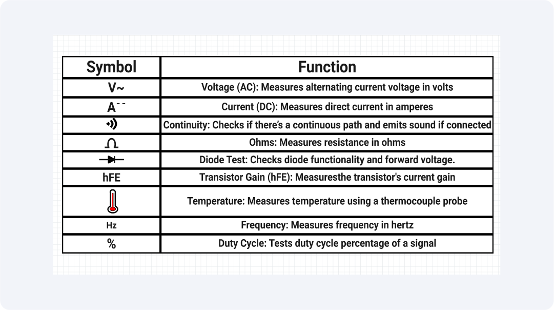
Multimeter Symbols
The multimeter symbols show different electrical measurements, enabling users to conduct tests accurately. These symbols also protect users from mistakes and help them with proper troubleshooting activities. To work with electrical devices, we need to know the measurement parameters, which include voltage, current, and resistance.
The essential symbols in electronics include V for voltage, A for current, and Ω for resistance. The icons on DMMs show users how to test diodes, perform continuity checks, and switch between AC and DC modes. These symbols make circuit analysis easy and enhance precision levels.
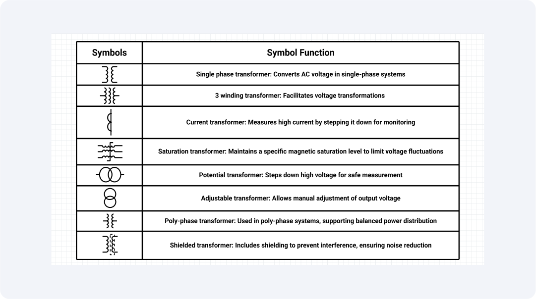
Transformer Symbols
Transformer symbols represent electromagnetic devices. They clearly show the types of transformers, including step-up, step-down, and isolation transformers. These symbols support correct circuit design and analysis processes.
A transformer has an iron core if two coils are connected through parallel lines and an air core if it has dashed lines. The ability to understand these symbols becomes crucial. It helps us design power distribution systems.
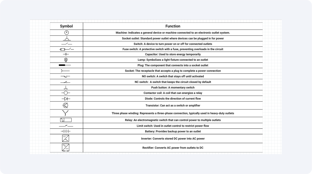
Electronic Outlet Symbols
It is crucial to use electronic outlet symbols in electrical circuit diagrams. They are used for socket outlets, switches, fuses, lamps, and plugs. The design simplicity is enhanced through these symbols. This helps explain the connections between devices. And the control mechanisms of electrical devices.
Power connections occur through socket outlets and plugs. Switches determine power distribution. Fuses safeguard circuits from overloads. Lamps show actual power conditions. These symbols help us design circuits accurately.
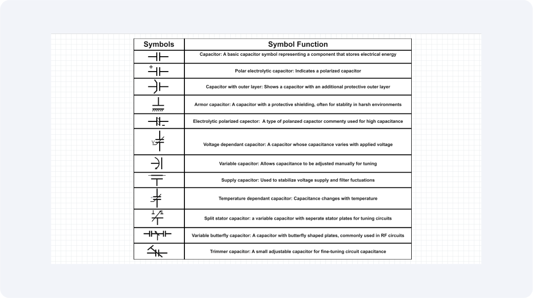
Capacitor Symbols
Capacitor symbols show components that store energy. They work as filters in circuits and are also smooth. There are two types of capacitor symbols: polarized and non-polarized.
The symbols make circuit designs simpler. They help designers select proper components correctly. Accurate symbol representation enables proper component placement. This results in enhanced system performance together. And it also provides safety improvements. Designers must understand these symbols to work effectively.
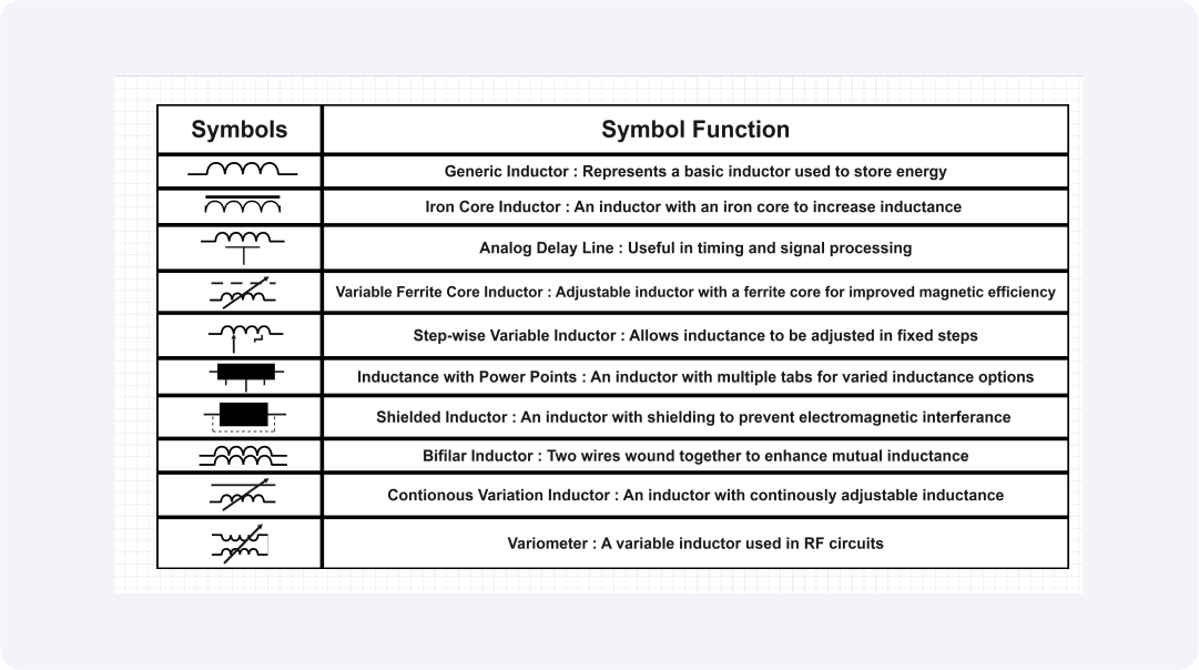
Inductor Symbols
The symbols for inductors represent devices that store magnetic field energy. They are used in filters, transformers, and oscillators. The symbols can also distinguish between air-core and iron-core inductors.
The use of proper inductor symbols makes it possible to design circuits accurately. And it improves the functionality of the circuit. The incorrect use of these symbols produces errors in the system. This can also result in performance degradation. Every electrical engineer needs to know these symbols.
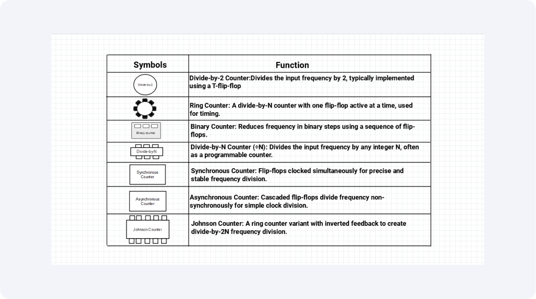
Frequency Divider Symbols
Frequency divider symbols denote components that decrease the signal frequency. These symbols are crucial when processing signals in digital systems, and they are also useful in communication systems and clock generation applications.
Using the right frequency divider symbols helps us create clear system designs, protecting us against misunderstandings in signal interpretation. Precisely representing these components in schematic diagrams enhances circuit reliability and improves functionality, preventing problems during the testing and implementation phases.
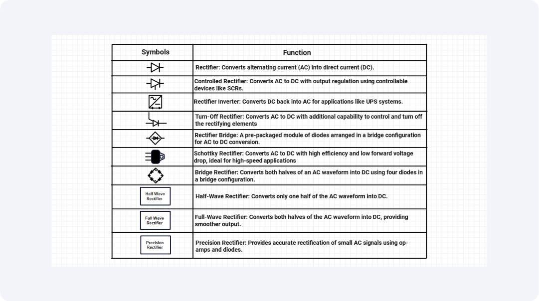
Rectifier Circuit Symbols
The symbols for rectifiers show how components convert alternating current into direct current. Power supply circuits alongside battery charging applications require these components. This helps them maintain a steady current flow in electronic devices.
The correct use of rectifier symbols during circuit design eliminates voltage conversion errors. Engineers benefit from proper schematic component representation, which enables them to identify parts swiftly, supports fast troubleshooting, and preserves system integrity throughout electronic systems.
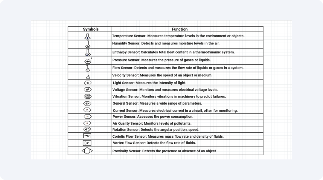
Sensor Symbols
We use sensor symbols to show devices that detect physical environmental changes. Real-time data collection is needed in automated systems. That depends heavily on these symbols in circuit designs.
Engineers can accurately identify components using the proper sensor symbol. This enables quick component recognition, which leads to smooth system installation. Standardized symbols also make troubleshooting easier. They create clear designs, which results in efficient system maintenance.
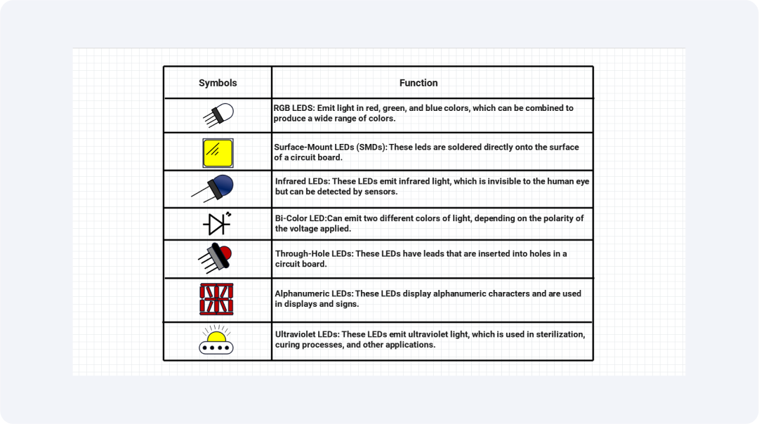
LED Symbols
Light-emitting diodes (LEDs) are essential visual indicators for circuit systems. Proper implementation of LED symbols improves system clarity and functionality. Devices that use these symbols include displays, signs, and appliances.
Standardized LED symbols prevent engineering errors during both design phases and assembly work. The symbols enable rapid component identification. This improves the accuracy of circuit flow. It streamlines maintenance operations during replacement and repair tasks.
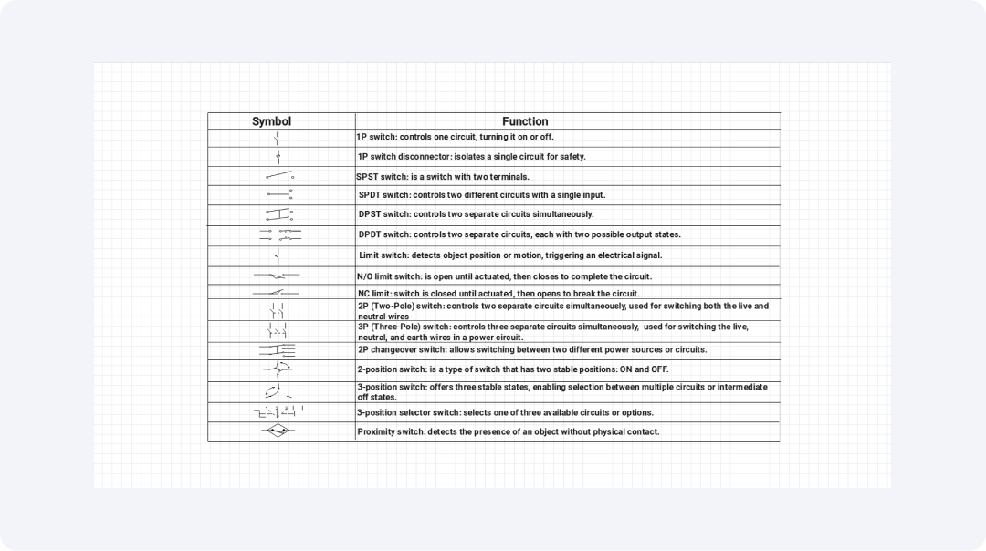
Switch Symbols
Electrical circuit control points in circuit diagrams require switch symbols, which help indicate their locations. Each symbol shows different switch types, including single-pole and double-pole, which regulate power distribution to distinct system elements.
Engineers need precise switch symbols to comprehend the operational design of a circuit. These symbols allow you to have a better electrical system design. And improves maintenance to achieve safe operational performance.
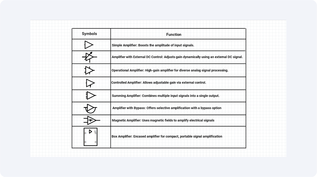
Power Amplifier Symbols
The symbols are vital in demonstrating amplification stages, guaranteeing signal quality in audio systems, and useful in communication networks and signal processing.
Proper use of power amplifier symbols leads to accurate circuit design. Engineers use these symbols to find vital components and demonstrate methods for enhancing signal power, enabling high-power, reliable systems.
Explore More Electronic Symbols on EdrawMax
EdrawMax is a visual collaboration platform with more than 26,000 symbols, which helps create diagrams. It also contains a sizable electronic symbol library for professionals and engineers.
These symbols serve both flexibility and accuracy. They help you efficiently simplify your diagram creation.
What Is Wondershare EdrawMax?
EdrawMax is great for generating professional designs. It has powerful diagramming functionality and a broad selection of design templates. It also has a large library of symbols and adaptable design capabilities. EdrawMax serves all types of users and provides highly effective tools for building flowcharts, network diagrams, and floor plans.
Some of the key features of EdrawMax include:
- Cloud-based for real-time collaboration
- Smart AI-assisted design tools
- Cross-device compatibility
- Cloud storage lets quick access and sharing of project files
How to Find More Symbols on EdrawMax?
Step 1Start EdrawMax
To begin, launch EdrawMax through the application and then log in.

Step 2Create a Project
To draw your diagram, select “New” and then “Blank Diagram”.

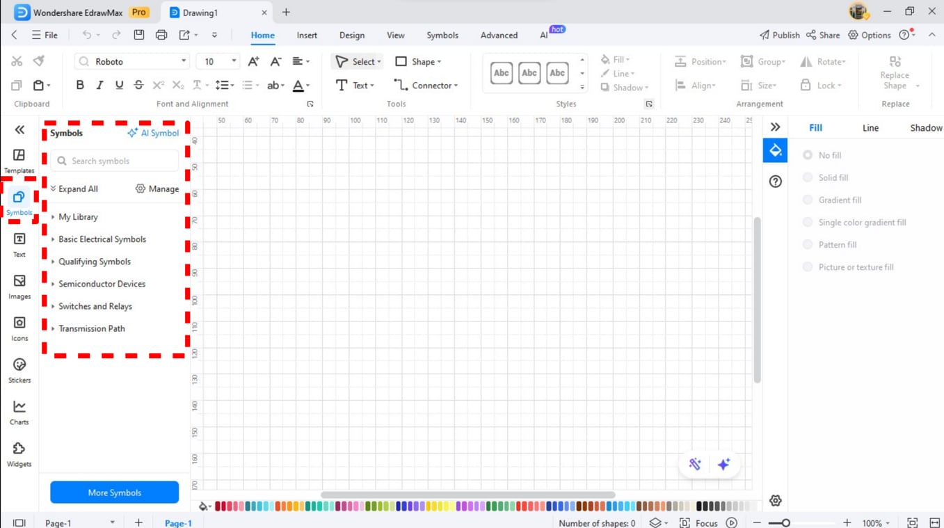
Step 3Go to Symbol Library
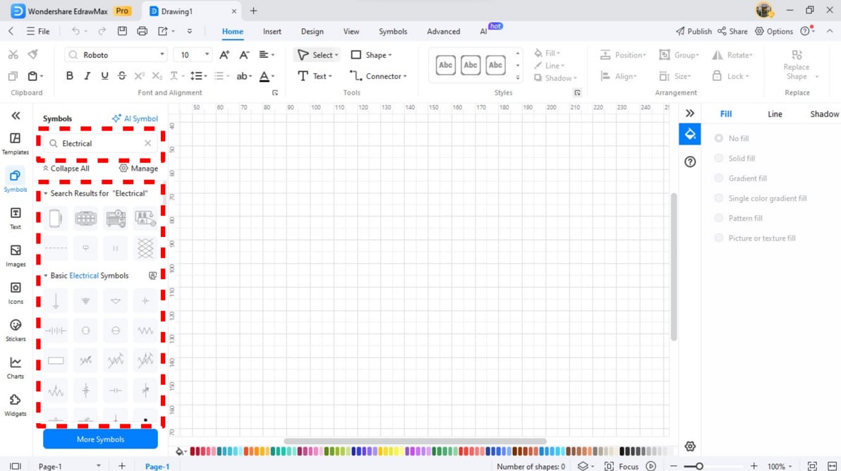
Click the "Symbols" panel on the left side of the workspace to access the symbol library.
Step 4Search for Symbols
The search bar helps you locate particular symbols. You can type the type of symbol you want to explore. And find types like "Electronic," "Flowchart," and "Network".
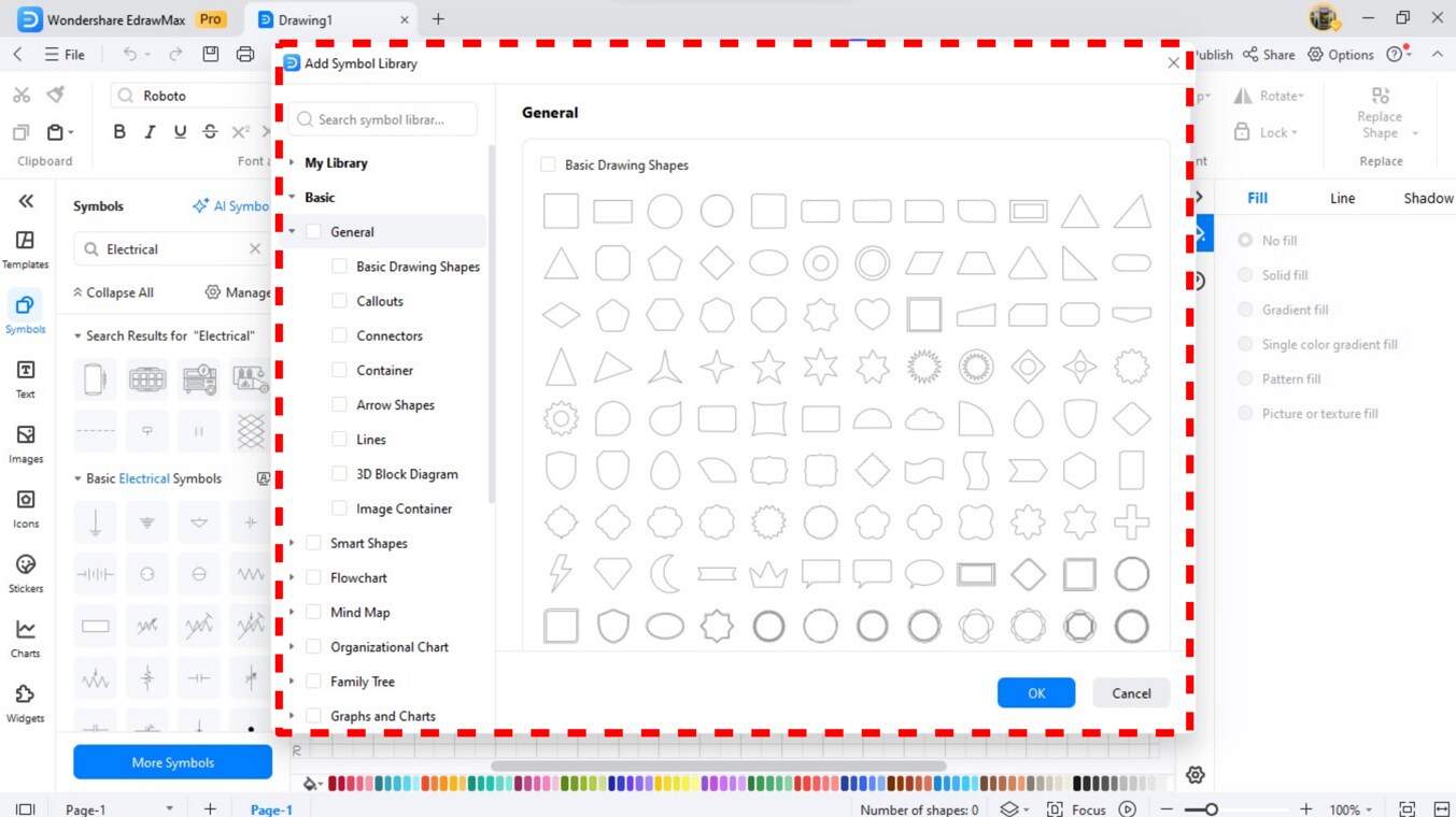
Step 5Download More Symbols
To access more symbols, simply click on "More Symbols" located at the bottom of the symbol library. A window will pop up. It will display various diagram symbol packs. And they will become visible after you click.
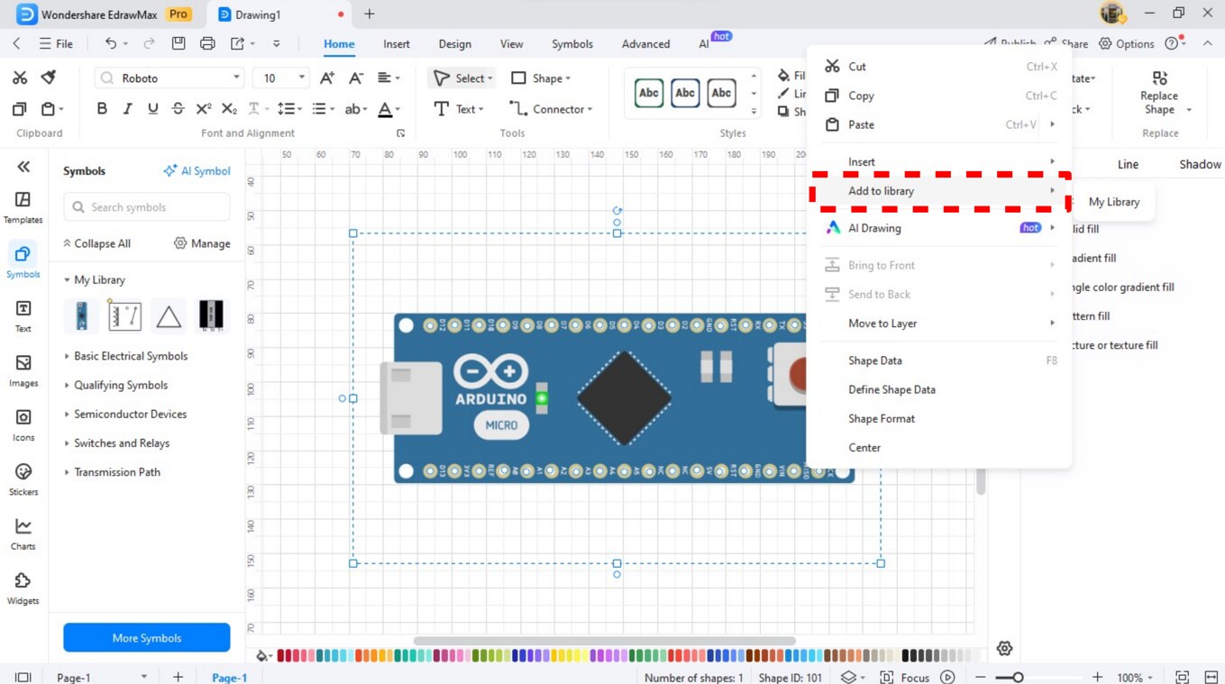
Step 6Add Custom Symbols
The platform allows users to build custom symbols which can be saved in their symbol library. Simply right-click on your symbol and select “Add to Library”.
Step 7Explore the Library
The symbol library gives you unprecedented options. It comes with a collection of 26,000 specialized electronic and technical symbols. Users can reach this feature through the platform interface.
How to Make a Circuit Diagram on EdrawMax?
EdrawMax's power made it easy to develop circuit diagrams. It offers user-friendly interfaces and a wide range of components. Users who create circuits need to follow only basic steps when using EdrawMax.
Step 1Open EdrawMax
Open the EdrawMax application. Log in through Wondershare ID, Google ID, or an alternative social account.

Step 2Select a Template
The first step is to select a design by searching "Circuit Diagram" within the template library to begin your project work.

Step 3Add Symbols
The symbol library provides a search interface. You can find resistors, capacitors, and transistors in them. You can drag them into their work area.
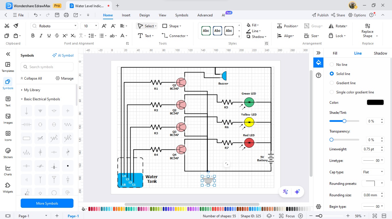
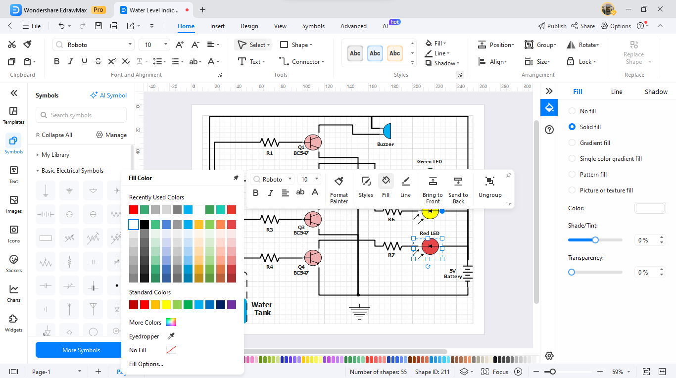
Step 4Customize Your Diagram
Adjusting component sizes can make your diagrams clearer. You can also change wiring connections while adding extra label texts to the design.
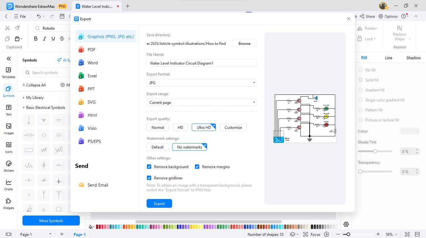
Step 5Review and Export
After completing the diagram, we can now export it. You can select between PNG, PDF, or JPEG file types for exporting and sharing purposes.
Ending Notes
Electronic symbols are essential for clear and precise circuit diagrams. With a well-organized library of over 26,000 symbols, EdrawMax helps users quickly create accurate and professional diagrams. Its intuitive design streamlines the process, making it a practical choice for beginners and experienced engineers.
So, why wait? Experience better electronic design through EdrawMax. Its user-friendly features help you complete projects faster. Start using it today to start enjoying the benefits.
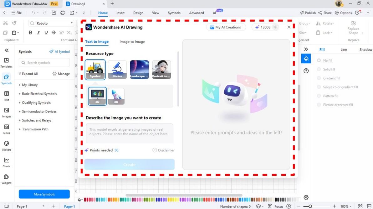
AI Diagram Generator
Enter your prompt. Upload files if needed. Generate diagrams, charts, or slides instantly.


