Anyone who wants to work with technical drawings must know equipment symbols. This means that these symbols make complex information to be easily communicated. Without them, the interpretation of the technical document would prove to be difficult.
Symbols are things we see every day in our lives. Whether it is traffic signs, electrical appliances, or others. For engineering and manufacturing industries, equipment symbols are very important. They assist the professionals in passing precise information in a short time and with huge details.
In this article, we emphasize the uses of equipment symbols in different fields. Mastering these symbols enables you to grasp and craft technical texts accurately. It will also improve communication in your work.
In this article
Part I. Equipment Symbols
Equipment symbols are essential for understanding technical diagrams. They represent various tools and functions, streamlining communication in fields like engineering and electronics. Let's look at some of the meaningful equipment symbols that can be useful in our lives.
Symbols for Multimeter
DC Current
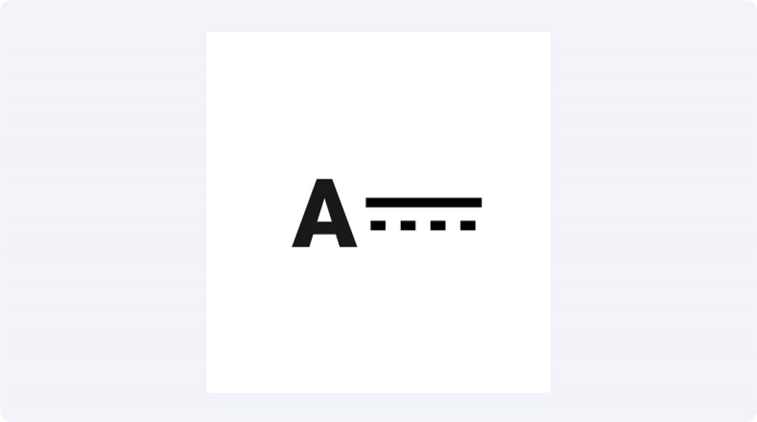
The DC Current symbol denotes direct current circulation and is measured in Amperes. It is used to measure the current in batteries or in any circuit where the current is steady. Highly useful when diagnosing car-related and electronics-related issues.
AC Voltage
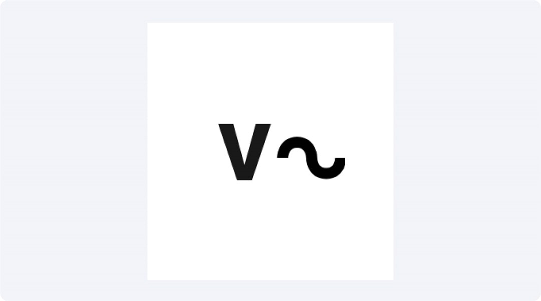
The AC Voltage symbol means the measurement of the voltage of the AC. Applied to the household and industrial electric distribution systems, it aids in confirming outlets and appliances. It measures the voltage across any circuit that has an AC supply where the current changes from forward towards reverse direction.
DC Voltage
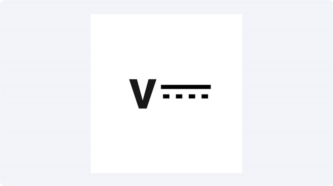
This symbol of DC Voltage is used to determine the direct current voltage which is used to determine the functioning of batteries and electronic circuits. It assists in the determination of voltage levels in devices that operate on one-directional current, for instance, portable electronics.
Alternating Current
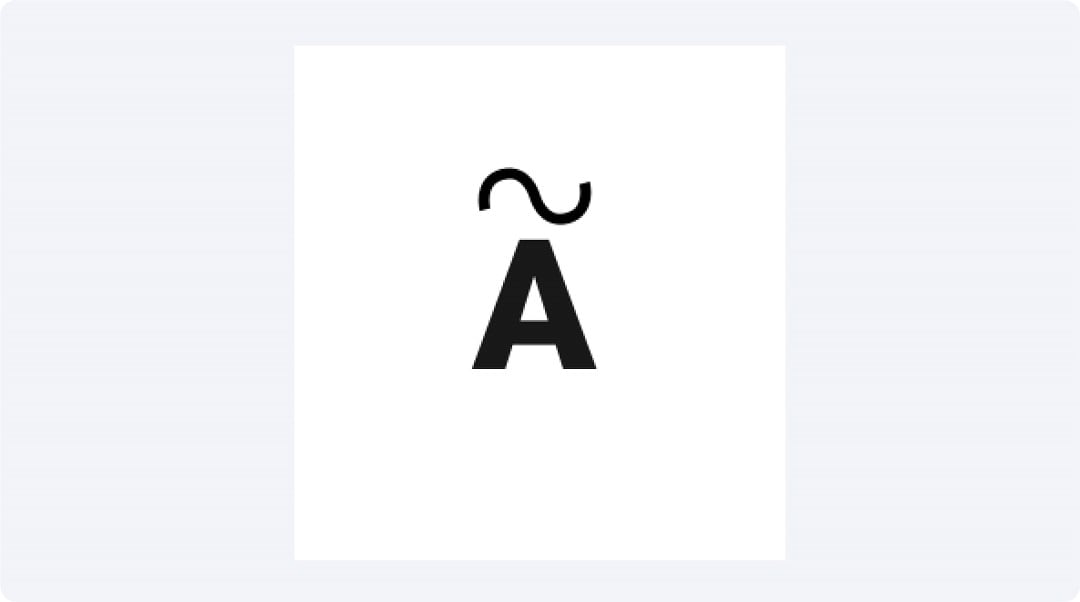
The Alternating Current symbol stands for the current that flows in different directions within a specific time frame. It is applied in almost all the home and industrial power networks. This symbol assists in providing a magnitude for the measurement and determination of the direction of the electric currents that run in AC driven gadgets.
Continuity
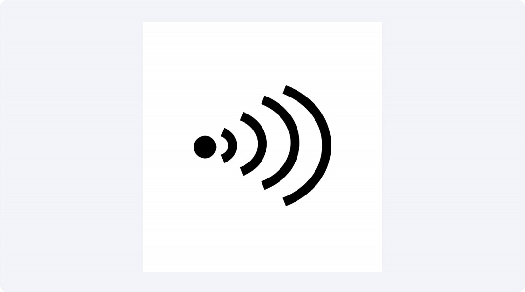
The Continuity symbol tests the integrity of a circuit. It is mainly applied in checking the wiring, fuses and various connections. A continuity means that the circuit will allow current through, meaning that all the connections are in place.
Ohms
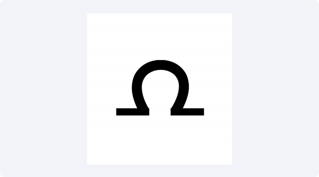
The Ohms symbol refers to electrical resistance which shows the amount of opposition to the flow of current in a component. It is employed in the testing of resistors and circuit paths; thus, components operate appropriately in a circuit.
Diode Test
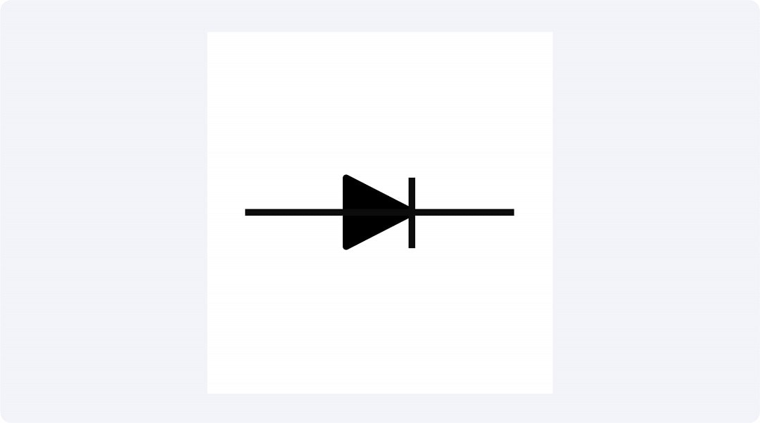
The Diode Test symbol tests diodes, devices permitting the current passing only from one end to another and not the other way around. It's used mainly in testing rectifiers as well as to confirm that diodes in any electrical circuit are working correctly.
Current Gain

The Current Gain symbol provides the amount of amplification that is produced by transistors. It is used in electronics to measure how much a transistor can amplify a signal because it is very essential in the design of amplifiers and in the fixing of amplifier problems.
Temperature
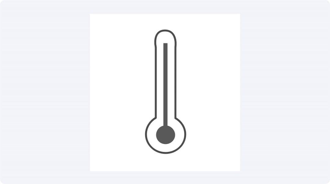
The Temperature symbol shows degrees of heat in circuits and components. It is applied to make sure devices work under certain temperatures that will prevent it from overheating and thus make the reliability of electronic systems better.
Frequency

Frequency shows how frequently an AC signal oscillates per second. It is applied in tuning of radios, testing of communication signals and ensuring that related gadgets work at optimum frequencies.
Duty Cycle

Duty Cycle gives a measure of the percentage of time for which a signal is on in a cycle. That is employed in PWM (Pulse Width Modulation) which is important for the regulation of motors and for controlling the brightness of lamps.
Part II. Make a PID with EdrawMax for Free
EdrawMax is designed for users to create equipment diagrams easily. It has an array of equipment symbols and templates making it easy to create technical drawings of various equipment. It is useful for engineers and useful for beginners as it helps to illustrate complex systems.
Step-by-Step Guide to Creating Equipment Symbols
Step 1: Log In to EdrawMax
You can visit the EdrawMax website to sign up for a free account or by logging into EdrawMax with Wondershare ID, google, Facebook, or Twitter.

Step 2: Making a New Project
Once logged in, click on "More”, and choose “Electrical Engineering”. Use one of the many templates available or proceed by choosing to start with a blank diagram.

Step 3: Select Symbols
From the symbol library, select the symbols you need. EdrawMax offers a comprehensive collection of symbols. You can also make your own symbols.

Step 4: Place Symbols
Drag and drop the selected symbols onto your workspace.

Step 5: Customize and Annotate
Customize the symbols and add annotations to provide more details about each component. You can change the size, color, and labels as needed.

Step 6: Save and Export
Once your equipment symbol is complete, save your project. You can also export it in various formats such as PDF, PNG, or SVG for sharing or printing.

Part III. Conclusion
In conclusion, learning how to identify symbols is crucial when working with instruments like the multimeter, for instance, the symbol AC voltage. These symbols assist the users in measuring voltage amounts in homes and industries to rectify problems that may occur with ease.
Knowing the symbol for the multimeter function and the multimeter ohm symbols is essential for testing electronic equipment. These symbols assist users to be able to measure such things as resistances, continuous amongst others. Understanding the symbols improves the process of troubleshooting.
