


Electrical engineering depends heavily on frequency dividers for their critical functionality. The devices operate to lower the amount of input signal cycles. Multiple applications benefit from these flexible components. They support operations in digital clocks and radio frequency systems.
To create well-designed circuit diagrams the knowledge of frequency divider symbols remains fundamental. This guide explores frequency divider symbol operations and their design value. So the instruction becomes effective in project development. EdrawMax stands as our introduction to a tool which enables users to build professional circuit diagrams.
In this article
All Common Types of Frequency Divider Symbols
In this section, we present 7 standard frequency divider symbol types for your reference. We hope this comprehensive symbol library will enhance your understanding of these essential circuit components. The Table of Contents below provides direct access to each specific symbol type.
7 types of frequency divider symbols
Divide by 2 Counter
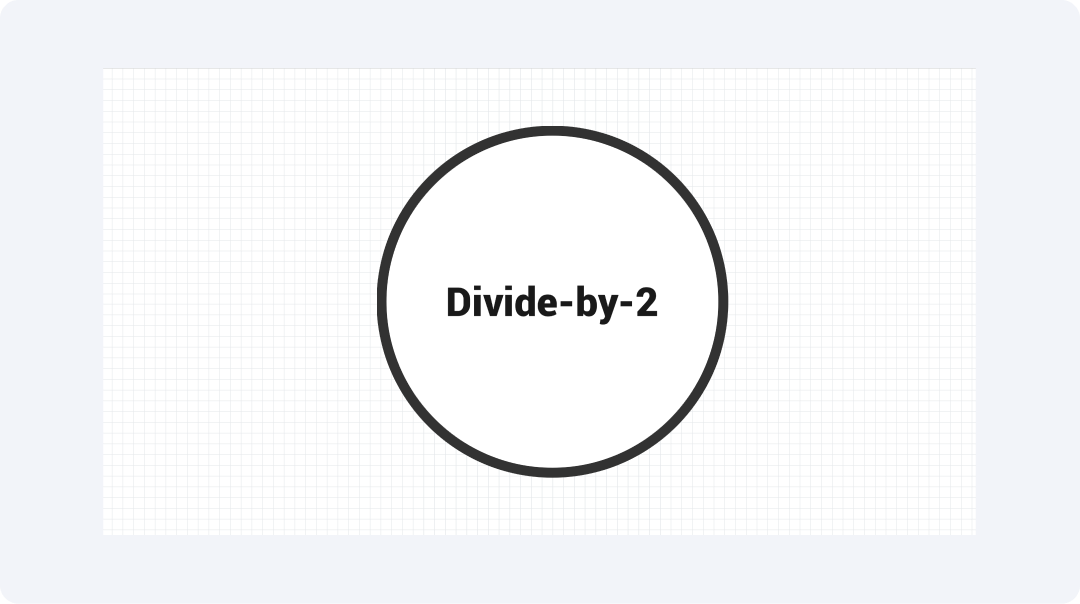
The Divide-by-2 counter functions as a fundamental digital frequency divider. It has a flip-flop that reduces input frequency by half. Each clock pulse triggers the counter to switch states and the output retains half of the input frequency.
The device plays a critical role in timing circuits because of its ability. A T-type flip-flop serves as the implementation block for the counter. It feeds the output signal back to the input to achieve reliable toggling. The basic design appears in multiple digital clock systems and microcontroller timing operations.
Ring Counter

The Ring counter consists of a shift register architecture with a circular configuration. This joins the output of its final flip-flop to the input of its initial stage. The ring counter maintains continuous circulation of 1 between its D flip-flops starting from the first stage.
The counter finds extensive applications in digital systems. It sequences output signals while performing multiplexing and demultiplexing operations. This output pattern of the device makes it appropriate for digital circuit applications. It is useful in automated control systems that need controlled signal activation.
Binary Counter
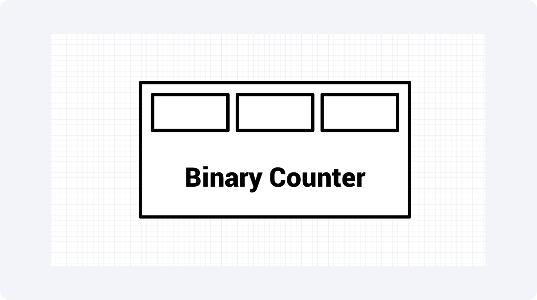
This device is known for increasing in a step-by-step binary pattern when triggered by clock pulses. It uses flip-flops to represent individual bits. The counter operates through a system where every bit changes state only after all preceding bits display a value of '1.' So we can generate and store sequential numbers.
T and JK flip-flops connected in series form the basis for this device. It is used in memory address generation and digital clock and timer systems for frequency division. Digital design and automation heavily depend on this device.
Divide by N Counter
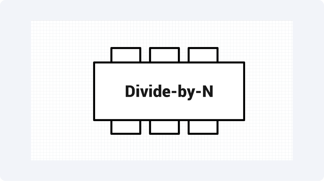
The Divide-by-N counter lowers input frequency by a specific factor, N. It counts N-1 steps before resetting. Each time N input pulses happen, it creates one output pulse. Digital systems can have custom timing intervals. We control precise frequencies to accomplish this.
The counter functions through flip-flops together with supplemental logic. This provides widespread application in synthesizers and customized timing circuits. The ability to divide frequency makes it necessary for digital communication systems.
Synchronous Counter
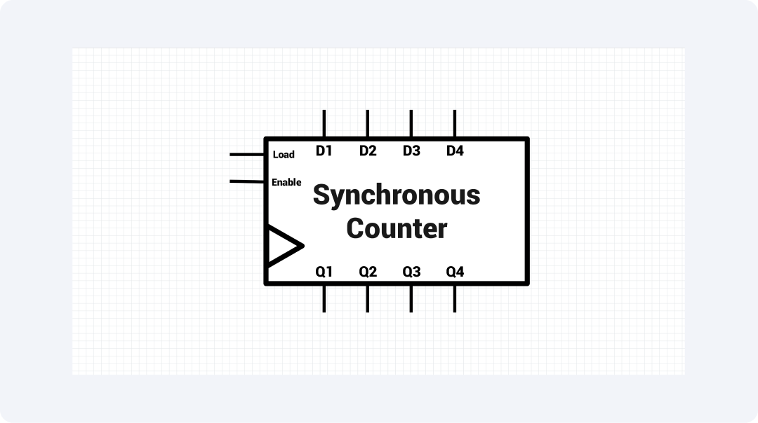
All flip-flops within a synchronous counter change state at once through the application of a common clock signal. The simultaneous changes between flip-flops through the common clock signal remove cumulative delays. This proves most useful when applied to high-speed frequency division systems.
The device contains parallel-connected flip-flops alongside combinational logic. This is used in counting purposes and measurement equipment through precise timing functions. The tool operates with exact results and high speed which makes it crucial for digital circuits.
Asynchronous Counter
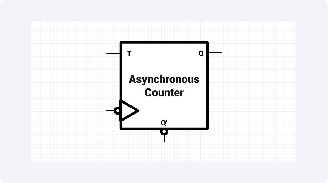
The Asynchronous counter acts like a ripple counter. Each flip-flop gets its trigger signal from the output of the flip-flop before it. The circulating state transitions through the counter. This results in minor time delays that enable an efficient frequency division process.
A ripple counter uses a simple design of flip-flops linked in a series. This powers low-power battery devices, basic counting operations, and time-sensitive tasks. The device works well in frequency division applications. It's simple design and low power needs make it efficient.
Johnson Counter
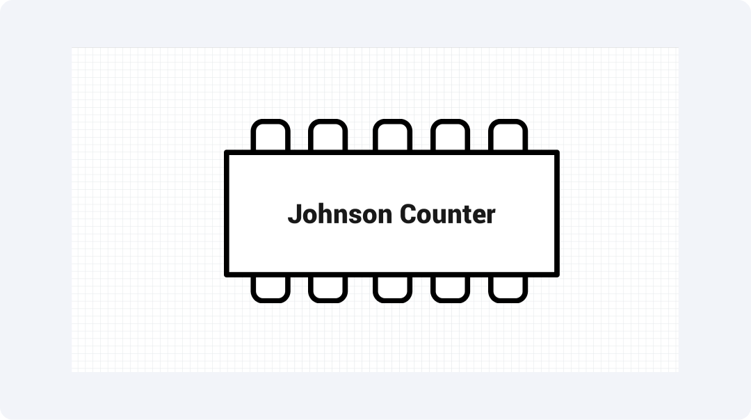
The Johnson counter is a modified ring counter. It uses inverted feedback to control state changes. The Johnson counter produces a special sequence of 2n states utilizing n flip-flops. This helps create efficient solutions for controlled frequency division and sequencing operations.
This counter looks like a ring counter. However, it uses the inverted output from the last flip-flop as its input signal. Counters are used a lot in digital control systems. They create reliable state changes. These changes help with making LED display patterns and controlling motor sequences.
Explore More Frequency Divider Symbols on EdrawMax
The symbol libraries in EdrawMax provide you with a broad range of frequency divider symbols. The tool gives users access to 26,000 electronic component symbols through its comprehensive diagramming system. You can find all the schematic requirements for precise design in EdrawMax. This is true whether you're a student engineer or a hobbyist.
What Is EdrawMax?
EdrawMax offers a simple interface. This makes it easy for users to create different diagrams and schematics. The diagramming app offers more than just basic features. It lets users choose from various visual formats. This makes it ideal for engineers, students, and professionals. They can create detailed technical illustrations with ease.
Let’s highlight some of the key features that make EdrawMax stand out in designing and diagramming:
- Offers an extensive collection of 26,000+ symbols for circuit and system design.
- Features a user-friendly drag-and-drop interface for seamless diagram creation.
- The system provides multiple editable templates to develop projects more efficiently.
- Runs smoothly across Windows, macOS, and Linux operating systems.
- Users can export their work in PNG, PDF, SVG, and multiple other file formats.
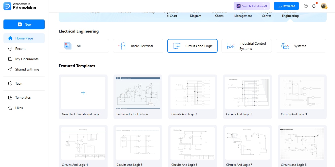
How to Find More Symbols on EdrawMax?
Finding the right symbols in EdrawMax is a straightforward process. Let’s break it down into simple steps:
Step 1Open EdrawMax and Login
Start by launching EdrawMax and then log in using Google, Facebook, or Twitter.
All templates below are free to access, view, and edit. You can download the template or the upgraded version for free as well.
Step 2Start a New Diagram
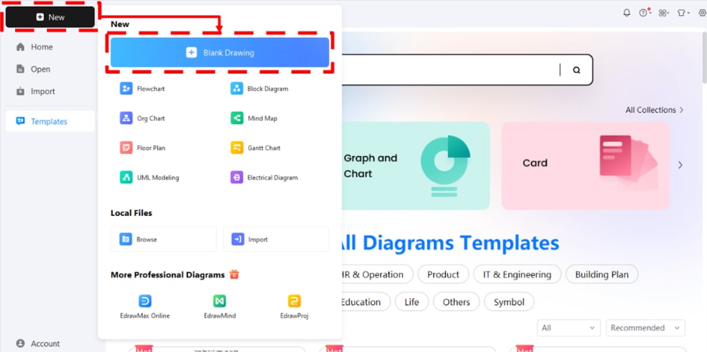
Click on the ‘New’ option. Select "Blank Diagram" from the list to begin creating a new workspace for your project.
Step 3Access the Symbol Library
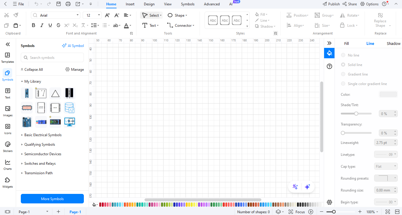
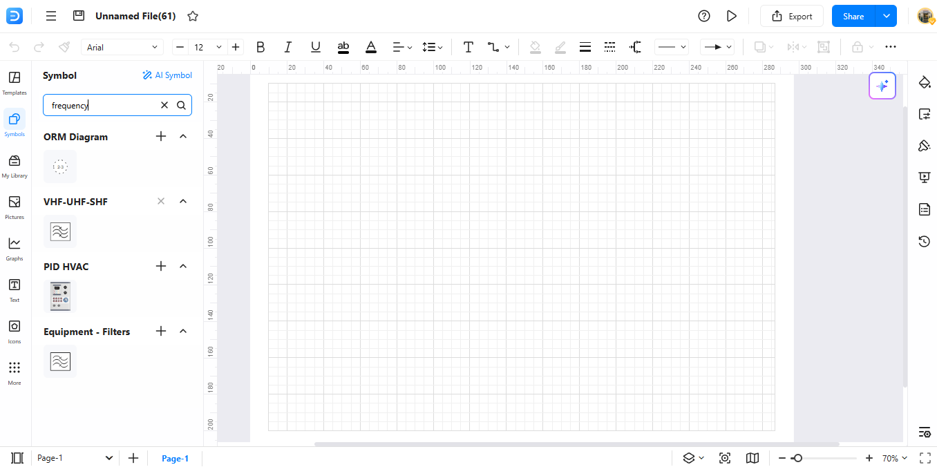
The left menu of your workspace contains symbols that you can access. The Symbols panel appears when you click the panel to view EdrawMax’s collection. A diagram type comes with specific symbols which users can easily use.
Step 4Search for Specific Symbols
The search bar in the ‘Symbols’ tab can be used to find more symbols. Users can locate symbols by using specific keywords.
Step 5Download Additional Symbols
Users can find the additional symbols by accessing the bottom of the collection. You can choose from available symbol packs through the menu which you can download. All selected packs from your custom library will automatically save.
Step 6Make Your Custom Symbols
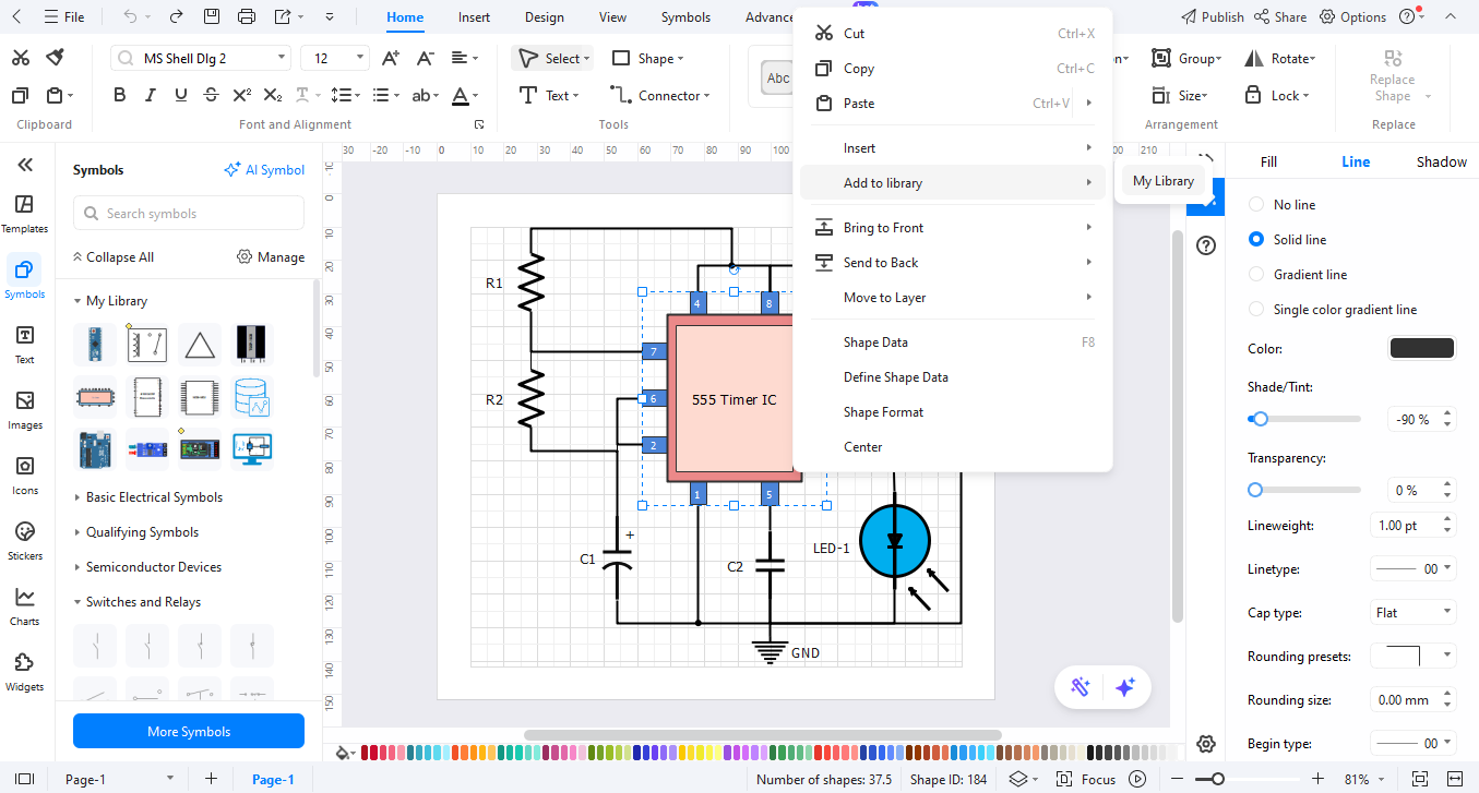
Right-click on new symbols to begin their customization. Right-click your diagram and choose "Add to Library." This lets you use it in future diagrams.
How to Make a Circuit Diagram on EdrawMax
Creating a circuit diagram with frequency dividers is a breeze in EdrawMax.
Step 01Open EdrawMax
Open the EdrawMax online tool on your browser through EdrawMax Web.
Step 2Create a New Project
Begin by launching a fresh diagram and selecting the “Circuit Diagram” template from the provided choices.
Step 03Add Circuit Symbols
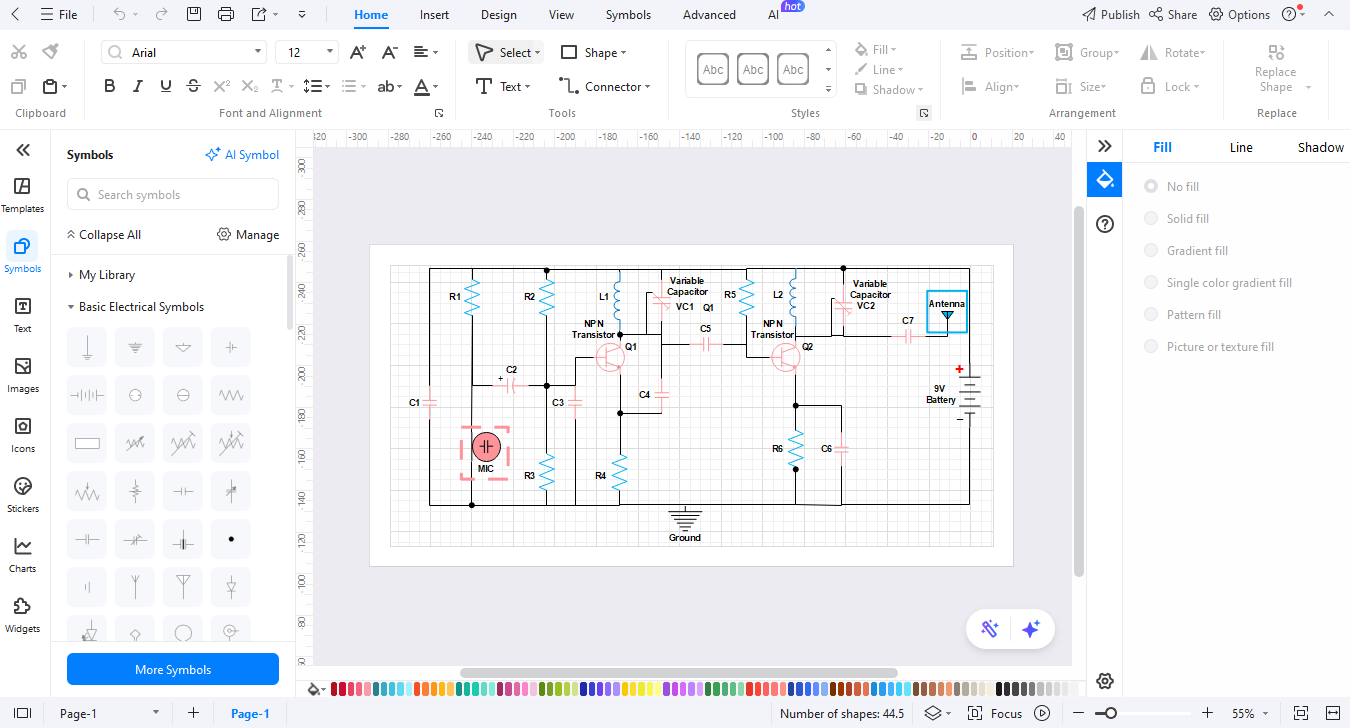
Search for the symbols in the library section before adding them to your drawing surface. Insert required circuit elements that include power sources and resistors.
Step 04Customize Your Diagram
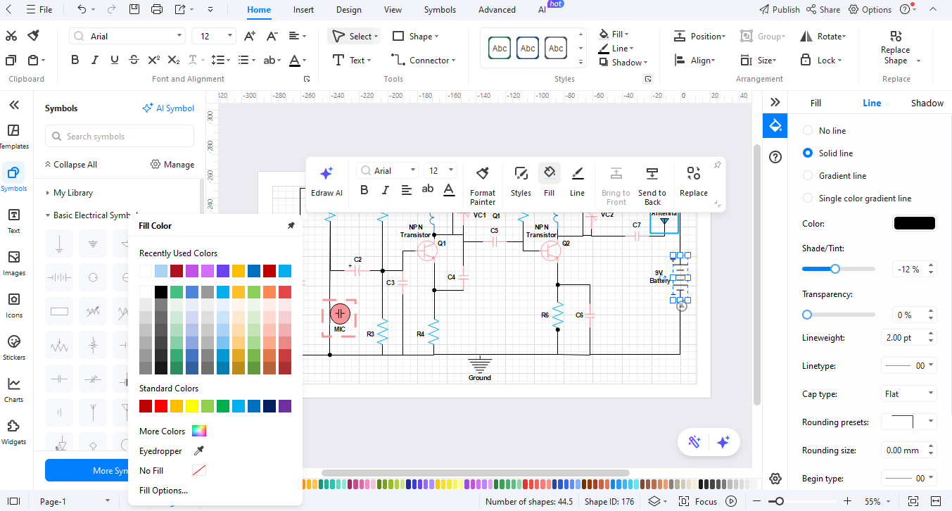
Utilize the connection tools to create wires between components to make correct connections. For clarity purposes utilize the text tool to label components and make annotations.
Step 05Export the Diagram
Click the “Export” button when satisfied to save your diagram in your desired output format among PNG, PDF, and SVG.
Ending Notes
The frequency divider symbols serve as tools for all electronic circuit practitioners. The visual elements simplify abstract concepts so users can understand them. EdrawMax allows skilled and unskilled users to generate professional diagrams with ease. The platform provides basic tools and extensive symbols for engineers, students and hobbyists.
EdrawMax provides an enjoyable platform to design circuits easily. It lets you make accurate frequency divider diagrams that present an attractive appearance. Starting your creations now will show you how straightforward it becomes to turn your thoughts into reality.
AI Diagram Generator
Enter your prompt. Upload files if needed. Generate diagrams, charts, or slides instantly.


