


The electrical circuit diagram requires fuse symbols as one of its essential components. The schematic drawings rely on standard fuse circuit symbols to represent protection equipment effectively. Symbols are key tools for engineers in circuit design, troubleshooting, and safety analysis.
This article looks at various fuse symbols. It explains their visual traits and why they matter in circuit drawings. Designing protective electrical systems demands a complete understanding of these visual symbols.
In this article
All Common Types of Fuse Symbols
There are 9 types of common fuse symbols. Let's check them all today!
- General Fuse Symbol (IEEE/ANSI Standards)
- General Fuse Symbol (IEC Standards)
- Old Symbol of Basic Fuse
- Thermal Fuse
- Fuse Switch
- Fast Blow Fuse
- Slow Blow Fuse
- Fuse with Striker
- Oil Fuse
General Fuse Symbol (IEEE/ANSI Standards)
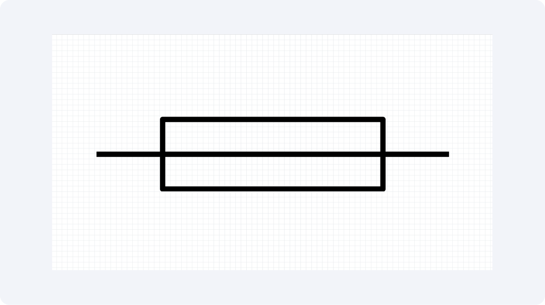
The IEEE/ANSI standards display the general fuse symbol as a rectangular shape with two connecting points on its end. The essential symbol stands for an ordinary fuse which offers protection from overcurrent. The general fuse symbol stands as the leading representation in every North American circuit diagram.
This standard symbol shows how the device works, not details about its construction. Electrical systems worldwide depend on general fuses. They help protect electrical parts by neutralizing harmful current surges.
General Fuse Symbol (IEC Standards)
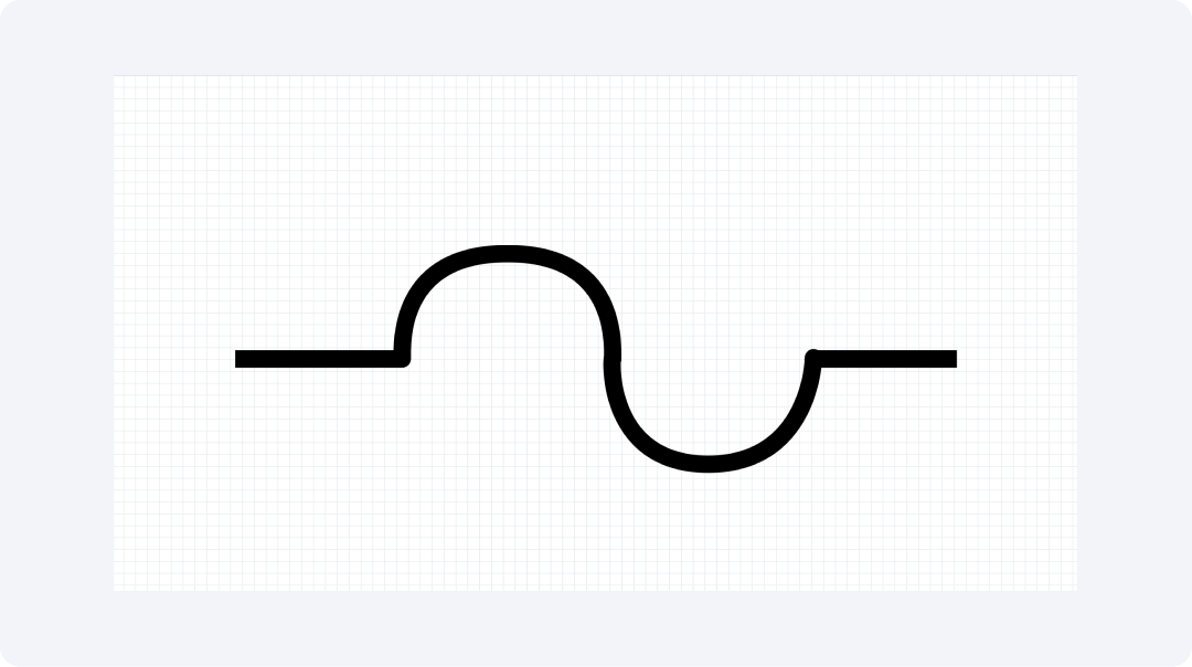
In IEC drawings, the fuse symbol looks like a straight line. It has a small change in the middle, like a tiny bump or a zig-zag. This representation is common in international circuit diagrams that follow IEC standards in Europe and globally.
The IEC fuse symbol is simple. This helps engineers add it to complex circuit diagrams without losing clarity. This symbol's simple design clearly shows where to place a protective device in a circuit.
Old Symbol of Basic Fuse
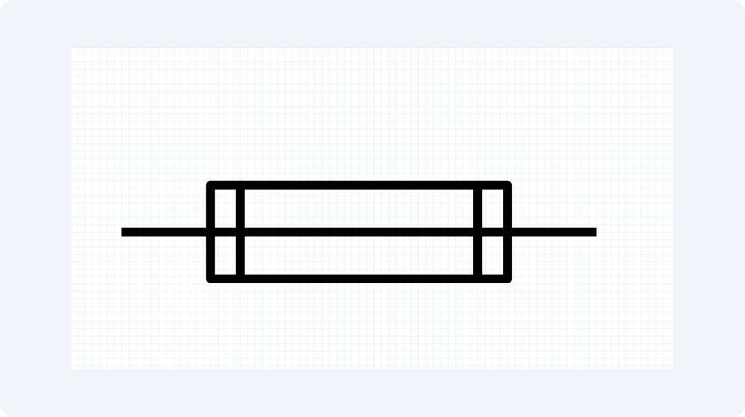
The traditional fuse symbol looks like a thin rectangle. It has attachment features at both ends. The traditional legacy symbol continues to appear in older documentation for educational purposes. The symbol illustrates basic glass tubes or ceramic fuses that contain wire components.
People should learn the old fuse symbol. It still appears in studies of historical documents for vintage equipment. The legacy symbol is found in systems that engineers must restore or update.
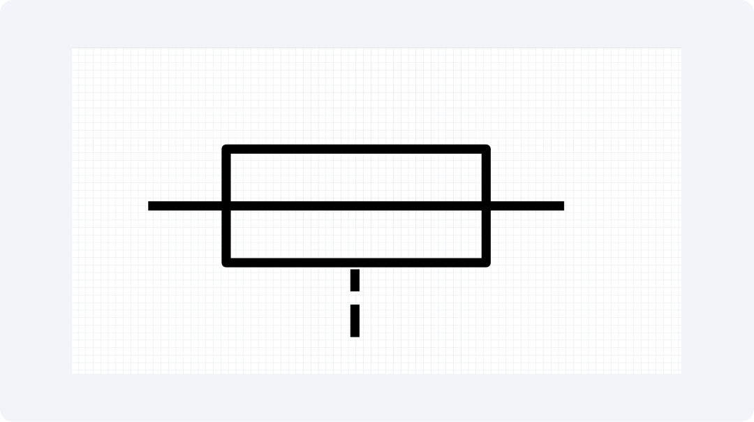
Thermal Fuse
The thermal fuse symbol looks like a normal fuse, but it has a tiny temperature indicator added. These components have a special feature: excessive heat detection. The thermal fuse is crucial for preventing heat buildup.
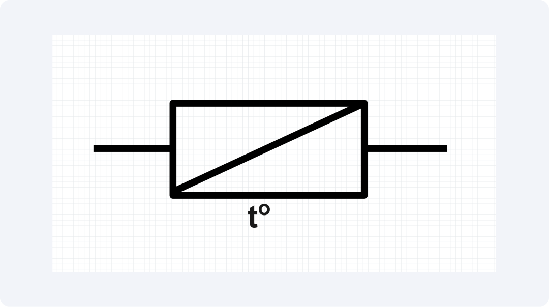
It safeguards important equipment that requires precise temperature control. The special symbol helps engineers find temperature protection elements in complex diagrams. This is especially useful for household appliances and heating systems.
Fuse Switch
A fuse switch symbol connects a fuse symbol to a switch. It does this by adding an operational line to the fuse symbol. The symbol shows a device that acts as an overcurrent protector and a manual disconnect.
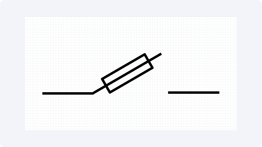
Fuse switches let maintenance workers safely interrupt circuits. They need to see that the circuit is disconnected before they start working. The symbol alerts engineers to two abilities combined in one unit.
Fast Blow Fuse
A fast-blow fuse has an "F" label or special markings near its basic symbol. Fuses designed to quickly respond to current spikes have markings. These markings show that they protect sensitive parts faster.
Any circuit with sensitive electronics needs fast-blow fuses. These fuses help prevent damage from brief overcurrent situations. This symbol helps engineers choose the right protection solutions. It quickly detects and responds to current spikes in time-sensitive systems.
Slow Blow Fuse
A "T" next to the standard fuse symbol shows it is a slow-blow fuse, or time-delay fuse. The symbol represents a protective element. It allows short-term surge currents but prevents long-term overload conditions.
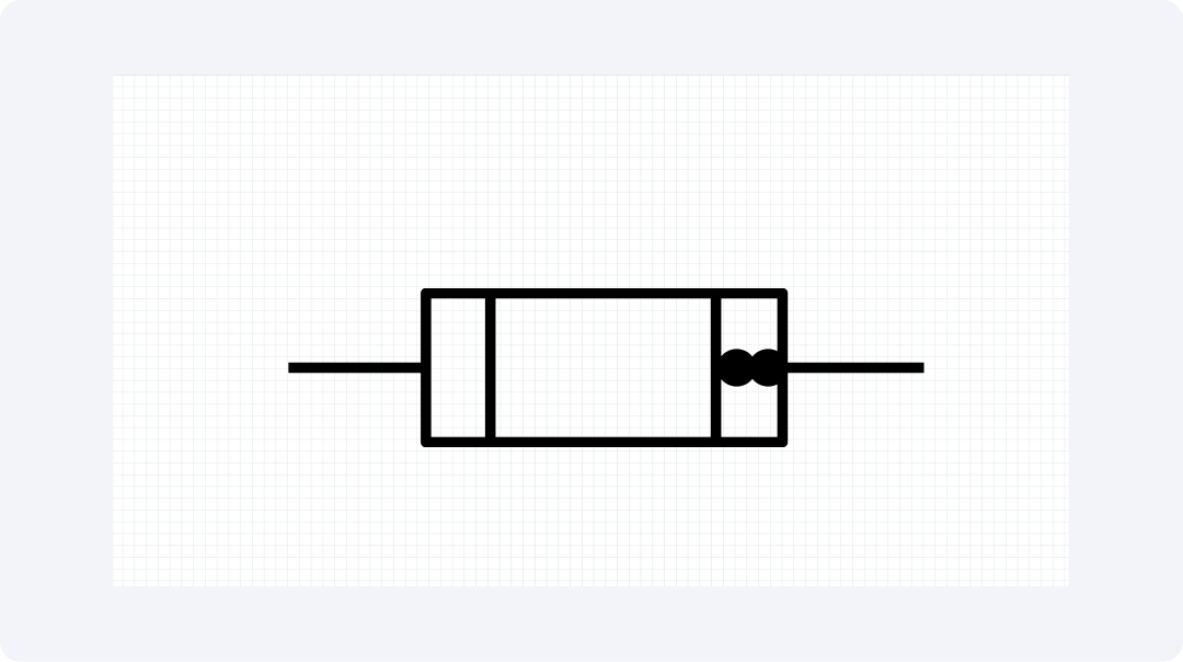
Slow-blow fuses are useful for motor circuits and equipment with normal inrush currents. The identification symbol helps engineers choose the right time-sensitive protection devices. This is important during circuit development for complex startup systems with motors, transformers, and capacitive loads.
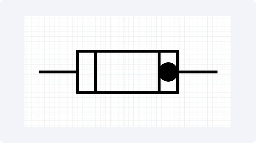
Fuse with Striker
The fuse with the striker symbol shows a basic fuse design. It also has a small striker symbol, which looks like a hammer-shaped bump. The symbol shows a fuse. It has a mechanical striker that works after the fuse fails. This striker activates extra protective devices.
A fuse with a striker function guards against electrical issues. It also has a feature that indicates when there's an overcurrent. This device's improved features are crucial for handling critical systems. They need quick responses when a fault occurs.
Oil Fuse
The oil fuse symbol shows a classic fuse design inside a frame. The enclosed space has small wave symbols, which represent oil immersion. The symbol shows oil-filled fuses. They use oil for cooling and suppression.
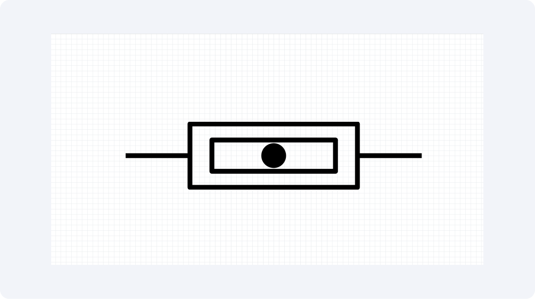
Oil fuses are mainly used in industrial power systems and electrical distribution networks. Power system engineers use this symbol to find parts in the substation and distribution diagrams. This is important because large fault currents need to be identified for safety.
Explore More Fuse Symbols on EdrawMax
The EdrawMax libraries have many fuse symbols for users to explore. This visual communication app has over 26,000 symbols you can configure. Multiple categories of electronic symbols are available in this collection. You can discover all the required components for circuit protection design through this platform.
What Is EdrawMax?
EdrawMax offers users a friendly visual interface. This software application functions beyond the production of drawings. Users can create various diagrams along with charts and visual elements on the platform. All users can benefit from EdrawMax. Its flexible interface works for any skill level. It covers all needs completely. Users can find useful engineering schematics, workflow plans, and student presentation materials here.
- The application gives users access to over 26,000 symbols. They can use these symbols to create various types of diagrams.
- The system includes a drag-and-drop interface that allows users to perform operations with ease. The design procedure becomes simple because of this system.
- Users can begin their tasks through selectable, editable templates that the software provides.
- This software provides perfect cross-device compatibility, operating on Windows, macOS, and Linux platforms.
- You can save all design files created with this software as PNG, PDF, SVG, and other formats.
How to Find More Symbols on EdrawMax?
Step 1Launch EdrawMax
Begin by accessing the EdrawMax application and then proceeding with your login.

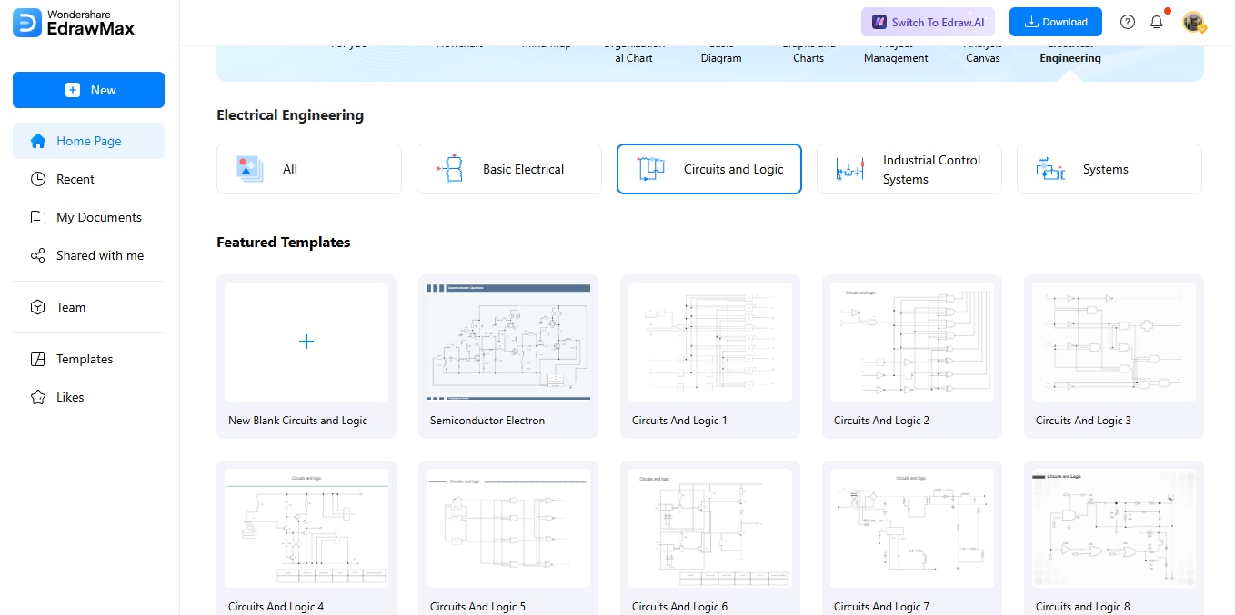
Step 2Create a New Project
The New tab function can be accessed from the interface. To establish your new project area choose "Blank Diagram" from the available options.

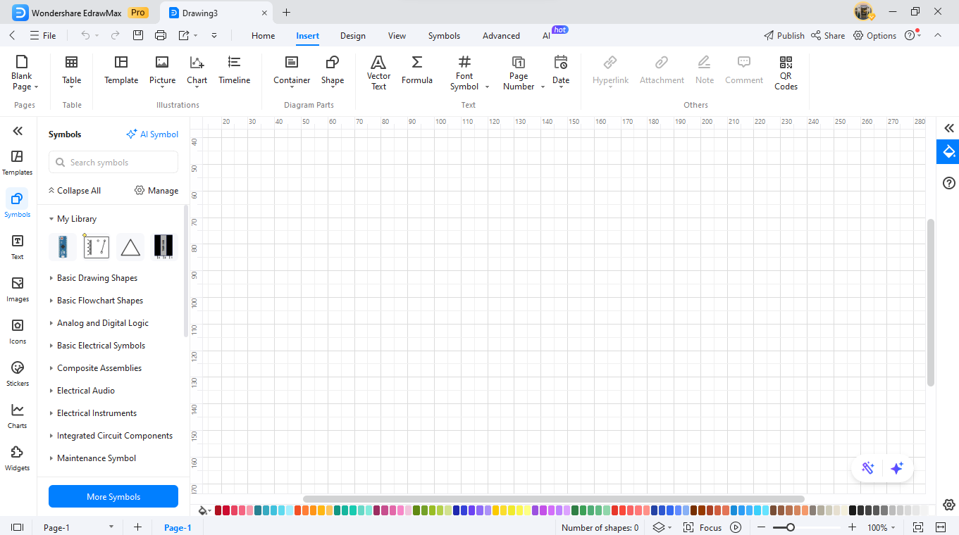
Step 3Access the Symbol Library
Use the symbols located on the left side of the screen. You can access all existing EdrawMax symbols through the Symbols panel. Different diagram types contain specific symbols throughout the collection of available elements.
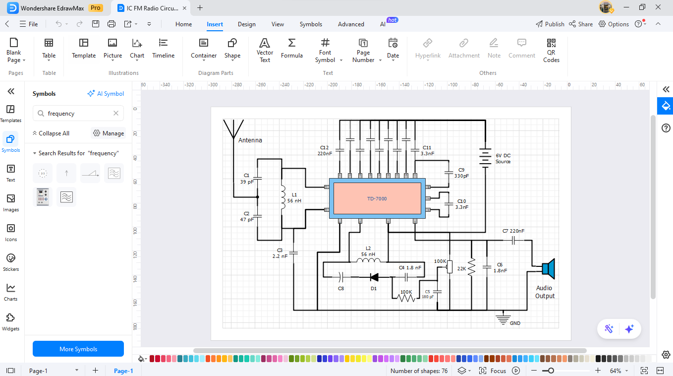
Step 4Search for Specific Symbols
You can locate the necessary symbol by entering its name in the search bar that resides on top of the workspace.
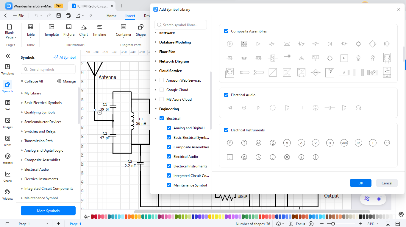
Step 5Download Additional Symbols
Open the symbol collection by selecting "More Symbols" from the bottom of the interface. Users can access downloadable symbol packages through the selection menu options. Choose the packs from the available list of options. Your custom library will display the saved symbols.
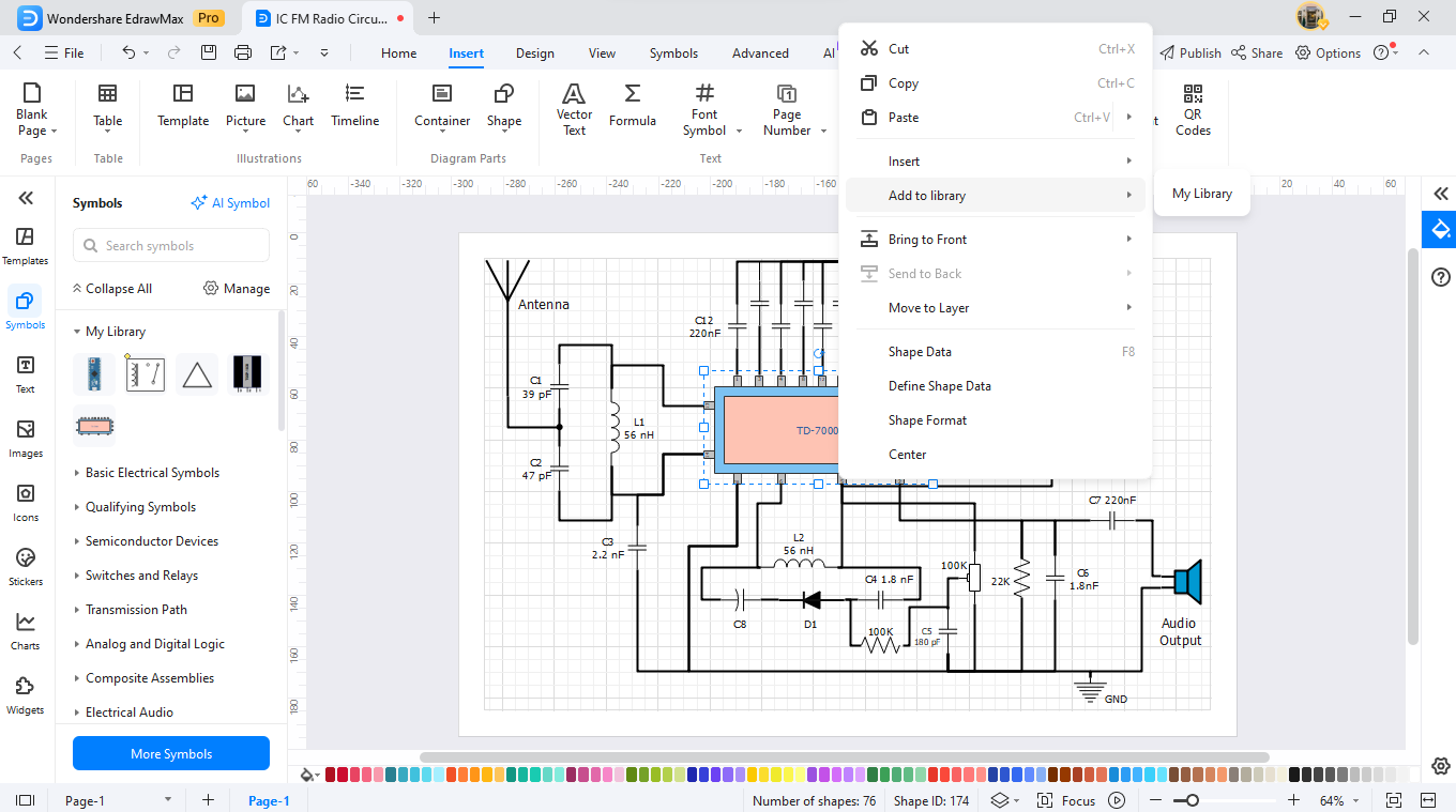
Step 6Create Custom Symbols
Users can use EdrawMax's straightforward drawing elements to construct custom symbols. You can initiate custom symbol design through a right-click action on new symbols found in the collection. The addition of new diagram components can be saved through the "Add to Library" selection.
How to Make a Circuit Diagram on EdrawMax
Creating a circuit diagram with frequency dividers is a breeze in EdrawMax.
Step 01Open EdrawMax
Open the EdrawMax online tool on your browser.

Step 2Create a New Project
Click "New". Begin your workplace by picking "Blank Diagram" or a "Template" from the available choices.
Step 03Add Circuit Symbols
Use the Symbol Library from the list of available tools. Insert all required fuse elements by dragging them from the tools menu into your current workspace.
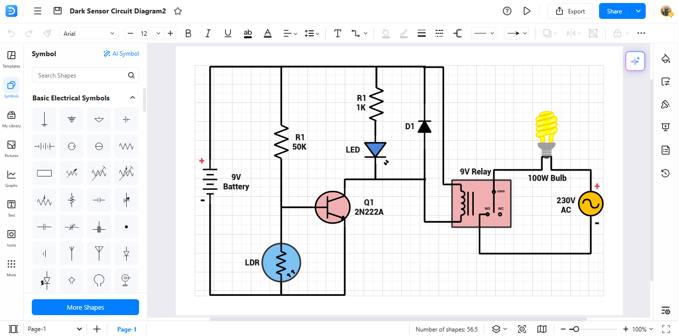
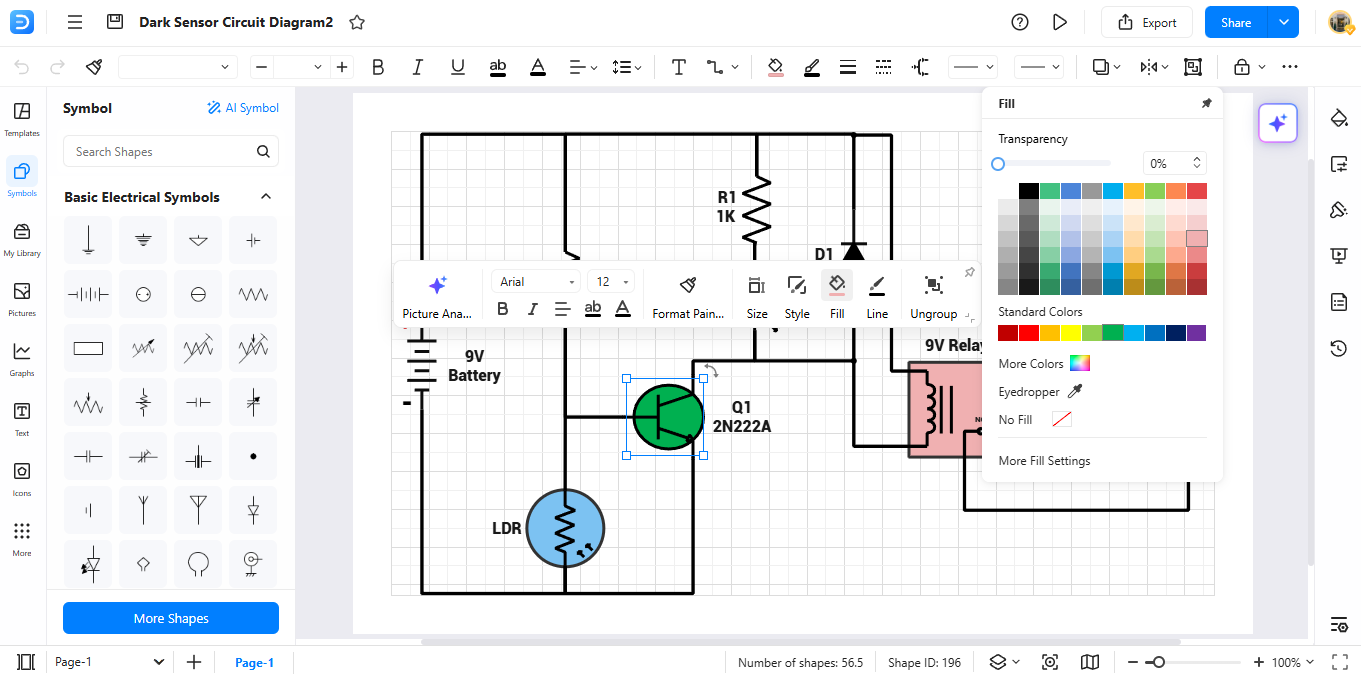
Step 04Customize Your Diagram
Provide relevant labels to each part of your diagram structure. The material should contain written information for improved comprehension. Use the available formatting tools to improve its look.
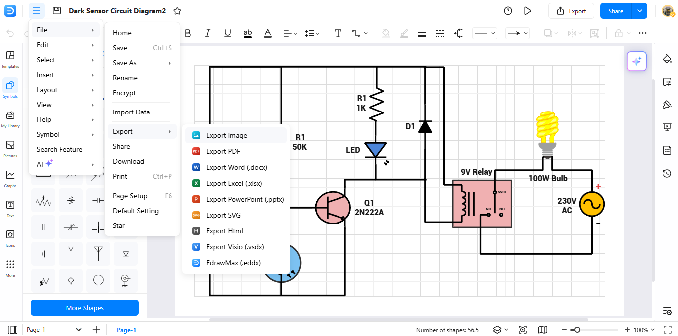
Step 05Export the Diagram
Once finished, review your diagram. Choose "Export" within the tools to save your design either as PDF, PNG or Visio file formats.
Ending Notes
Knowledge of fuse symbols is vital for anyone in electrical circuit design and electronics. Safe development of reliable systems relies on understanding these symbols and how they work. They provide a precise visual representation of protection devices.
Knowing fuse symbols helps engineers create better circuits. It also makes maintenance tasks easier. Identifying different visual symbols is key to protecting circuits. You can create clearer diagrams for your projects with EdrawMax. This app offers over 26,000 symbols, including standard fuse symbols. You can easily add elements to your diagrams. EdrawMax is easy to use.
AI Diagram Generator
Enter your prompt. Upload files if needed. Generate diagrams, charts, or slides instantly.


