


Inductor symbols are vital in circuit design. They are the standard way to represent inductors in electrical diagrams. These schematic symbols ensure clear, consistent communication of a circuit's function. Knowing inductor symbols and their types is key. They help design efficient circuits and troubleshoot problems.
This article gives an overview of inductor symbols. It covers their types, standard forms, and importance in electrical schematics. By mastering these symbols, you can improve your circuit design and troubleshooting skills.
In this article
All Common Types of Inductor Symbols
- Generic Inductor Symbol
- Iron-Core Inductor Symbol
- Variable Ferrite-Core Inductor Symbol
- Variometer Symbol
- Bifilar Inductor Symbol
- Shielded Inductor Symbol
- Stepwise Variable Inductor Symbol
- Continuous Variation Inductor Symbol
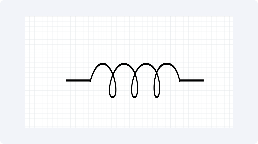
Generic Inductor Symbol
The generic inductor symbol represents an inductor without a magnetic core. It features a basic coil shape with no extra markings. These inductors are ideal for high-frequency uses, like antennas and RF circuits. They have minimal core losses and stable performance. Their simple symbol ensures clear identification in circuit diagrams, making it easier for engineers to understand their role in design.
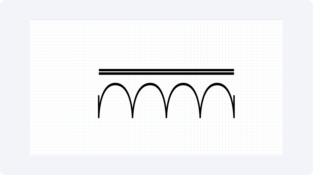
Iron-core Inductor Symbol
The iron-core inductor symbol shows a coil with parallel lines through it. This indicates an iron core. This core boosts inductance. It makes the inductor fit for low-frequency circuits, like power transformers and audio systems. The symbol's design shows the core material's impact on performance. It helps engineers pick the right component for specific applications.
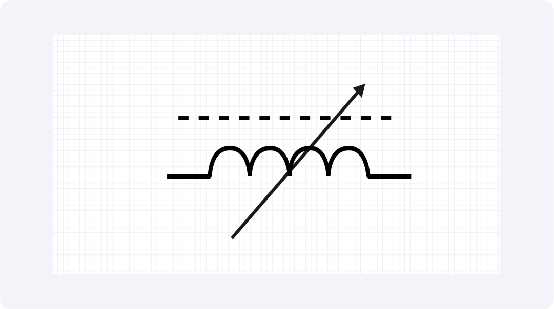
Variable Ferrite-core Inductor Symbol
The symbol for a ferrite-core inductor looks like a typical inductor but has important adjustments. It has a central core that represents the ferrite material. There’s also a graphic that shows how inductance can change. These inductors use magnetic cores made from ferrite.
Ferrite is great for high-frequency applications due to its low-loss characteristics. These inductors are used in tuning circuits and transformers. They often need to change circuit performance for filtering applications.
Variometer Symbol
The standard variometer symbol features an arrow across the coil. This arrow shows that the inductance is adjustable, meaning the device can change its inductance as needed.
Variometers are often used to tune frequencies in radio and oscillator circuits and control systems. The arrow in the symbol shows adjustability, making it easy to find in schematics.
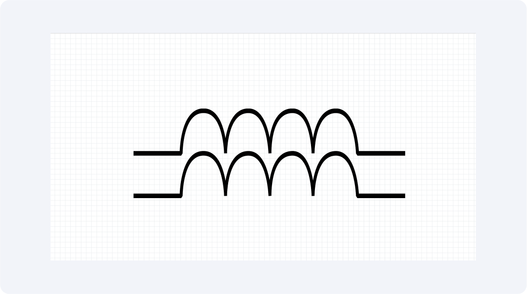
Bifilar Inductor Symbol
A standard bifilar inductor symbol has two parallel lines representing the two intertwined conductors surrounding a core. Standard inductor symbols show a single helical shape. Bifilar inductor symbols need two horizontal lines or notes showing the dual winding.
These devices serve applications needing vital two-wire links, including transformer operations and EMI reduction systems.
Bifilar inductors have wires that are tightly connected. This gives them unique behavior and mutual inductance. It sets them apart from regular inductors. This symbol enables quick circuit identification. It shows where two inductors join for noise reduction and energy transfer.
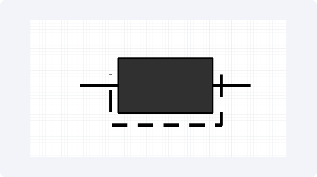
Shielded Inductor Symbol
A shielded inductor symbol shows a box around the coil. It indicates the inductor's resistance to electromagnetic interference (EMI). Shielded inductors protect against EMI. They suit applications, like audio systems and communication devices, that need noise reduction. The symbol represents shielding functions in diagrams while staying accurate.
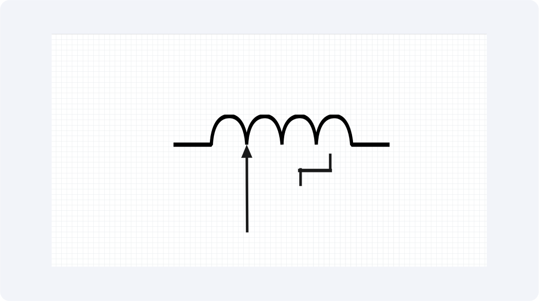
Stepwise Variable Inductor Symbol
Stepwise variable inductor symbols represent discrete, adjustable inductors, which differ from continuous inductors in unique representation. The symbol shows an inductor coil with markings through small steps or switch-like icons. It represents specific adjustable inductance ranges.
Stepwise variable inductors work in applications that need precise inductance control. This is true even when continuous change options are unavailable.
Tuning circuits use stepwise variable inductors. They are in audio equipment and radio frequency (RF) applications. The symbol distinguishes these inductors by showing preset inductance. This helps designers know their exact function in circuit diagrams.
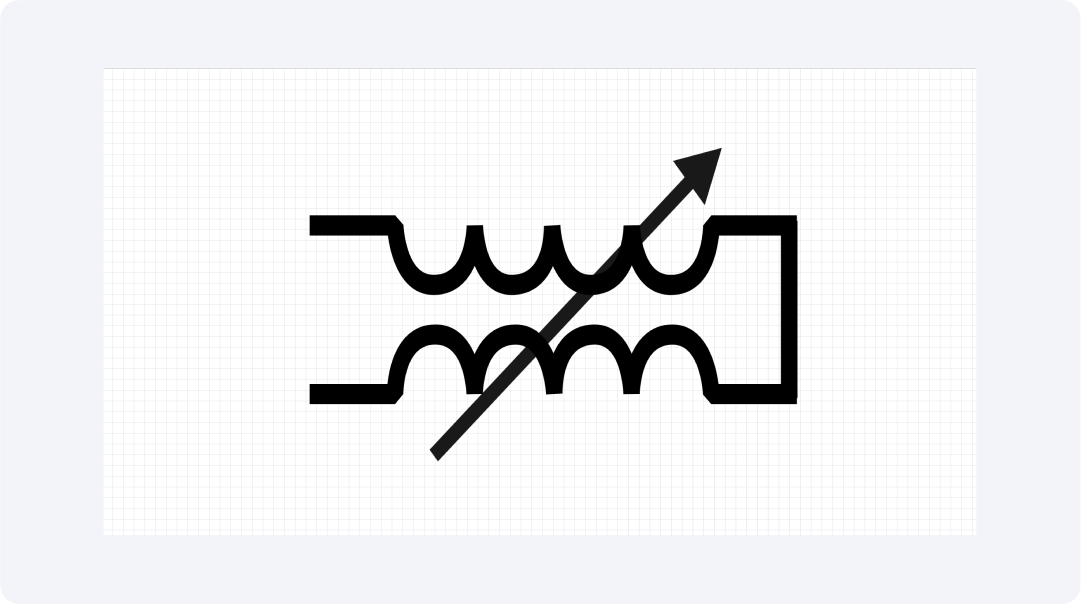
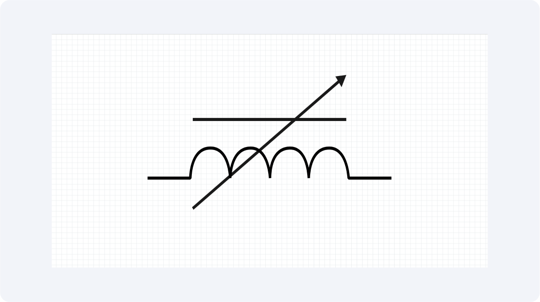
Continuous Variation Inductor Symbol
The continuous variation inductor symbol shows an inductor. Its inductance can be tuned between different values. The symbol shows an inductor coil design. It has markings that show the component can adjust its inductance without interruption. An arrow indicates adjustable properties in inductor symbols like variable capacitors and resistors.
RF circuits need accurate inductance regulation. They often use continuous variance inductors. These inductors allow for precise control of circuit behavior. Schematic diagrams show adjustable inductors with a special symbol. This symbol indicates their tunable and flexible properties in electronic designs.
Explore More Inductor Symbols on Wondershare EdrawMax
EdrawMax has many inductor symbols and other schematic components for your designs. It allows visual collaboration on a platform with over 26,000+ symbols. It includes electronic symbols made for circuit design. EdrawMax’s symbol libraries give designers what they need. They can create precise electrical schematics.
EdrawMax is a complete app that provides designers with circuit models, troubleshooting tools, and resources on inductor symbols. Engineers can access a vast library of standard, customizable, and niche symbols, which can simplify their designs and improve their technical communication.
What Is Wondershare EdrawMax?
EdrawMax is a visual collaboration platform. It promotes efficient diagramming for all users. This versatile tool generates high-quality diagrams for multiple audiences. It has an interface that is easy for users to navigate. EdrawMax's design and features make it easy for users to bring their ideas to life. Key features of EdrawMax are:
- Users can access over 26,000+ electronic component symbols. They include inductors, capacitors, and other schematic elements.
- It offers over 210 types of diagrams. This includes flowcharts, electrical schematics, network plans, and more visuals.
- Users enjoy the simple design. With drag-and-drop tools, anyone can make great diagrams regardless of skill level.
- It's available on Windows, Mac, and Linux, and a web version allows easy access on any device.
- Users can achieve real-time collaboration through Smart Construction. It lets teams create project markups.
- With integration into Microsoft Office and Google Workspace, users experience better productivity benefits.
- Exports diagrams in formats like PDF, PNG, SVG, and Visio.
- The user builds project momentum with various templates and design samples.
How to Find More Symbols on EdrawMax?
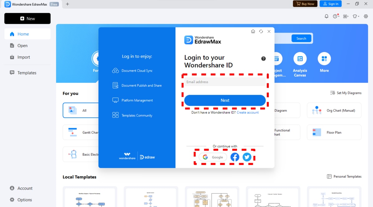
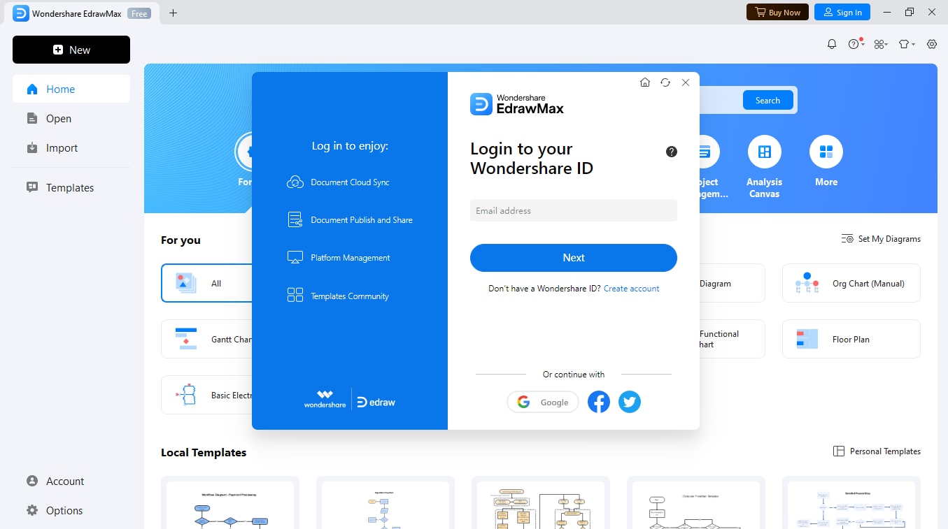
Step 01Launch EdrawMax
Open EdrawMax on your device to start. Then, log in with your Wondershare ID.
Step 2Start a New Diagram
In the main menu, choose "New," then select "Blank Diagram." This will give you an empty workspace to start your design project.

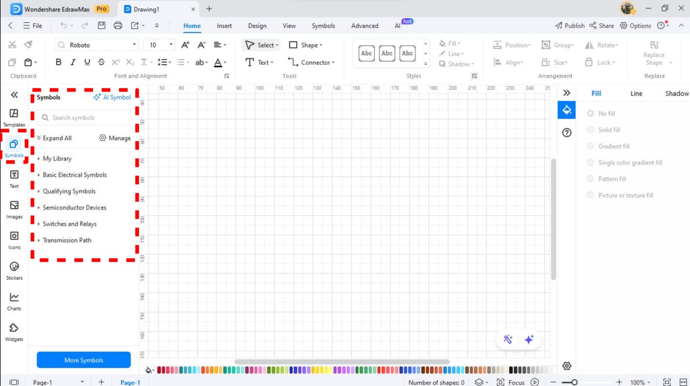
Step 3Open the Symbol Library
The "Symbols" tab is on the left side of the workspace. Click on it to explore various built-in symbols organized by purpose.
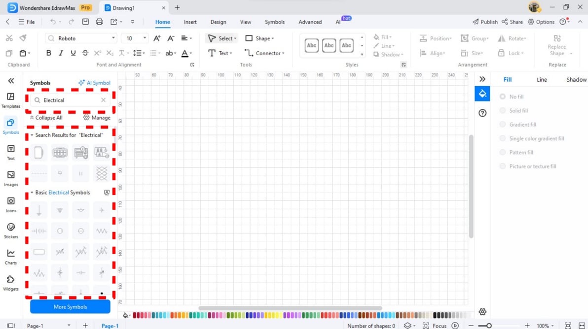
Step 4Locate Specific Symbols
Use the symbol library's search bar To find symbols faster. Entering keywords can help you refine your search.
Step 5Access Additional Symbol Packs
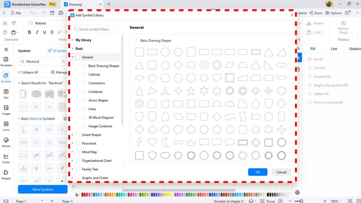
Select "More Symbols" at the bottom of the symbol library. A new window will show symbol packs available to you. Pick from these packs to expand your library options.
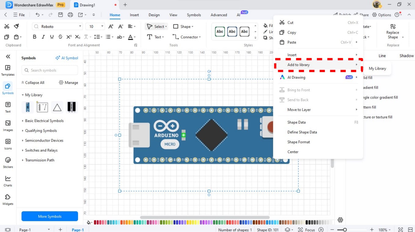
Step 6Customize and Save Your Symbols
Use EdrawMax to create custom symbols for your project. To save a symbol, right-click it and select "Add to Library." This stores it in your collection for future use.
Step 7Explore the Library
Explore the library to make the most of EdrawMax software. It features over 26,000+ symbols designed with expertise. These will enhance your diagrams for electronic and technical applications.
How to Make a Circuit Diagram on Wondershare EdrawMax?
Step 1Open EdrawMax
Launch EdrawMax and log in using your Wondershare ID. Click "New" on the main menu to start your project.
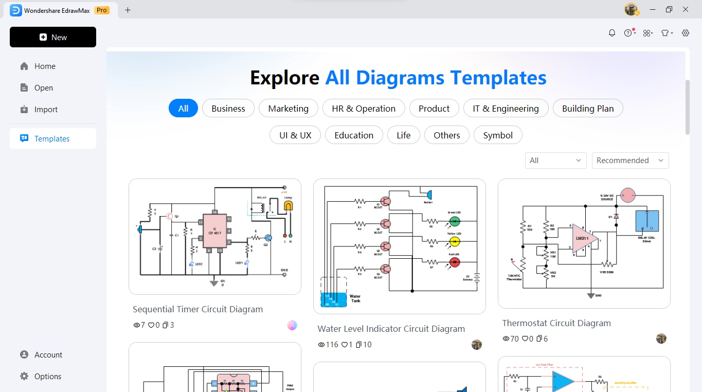
Step 2Select a Template or Start from Scratch
Select the "Electrical Engineering" area on the interface. Select a blank workspace or use a template to build your schematic.
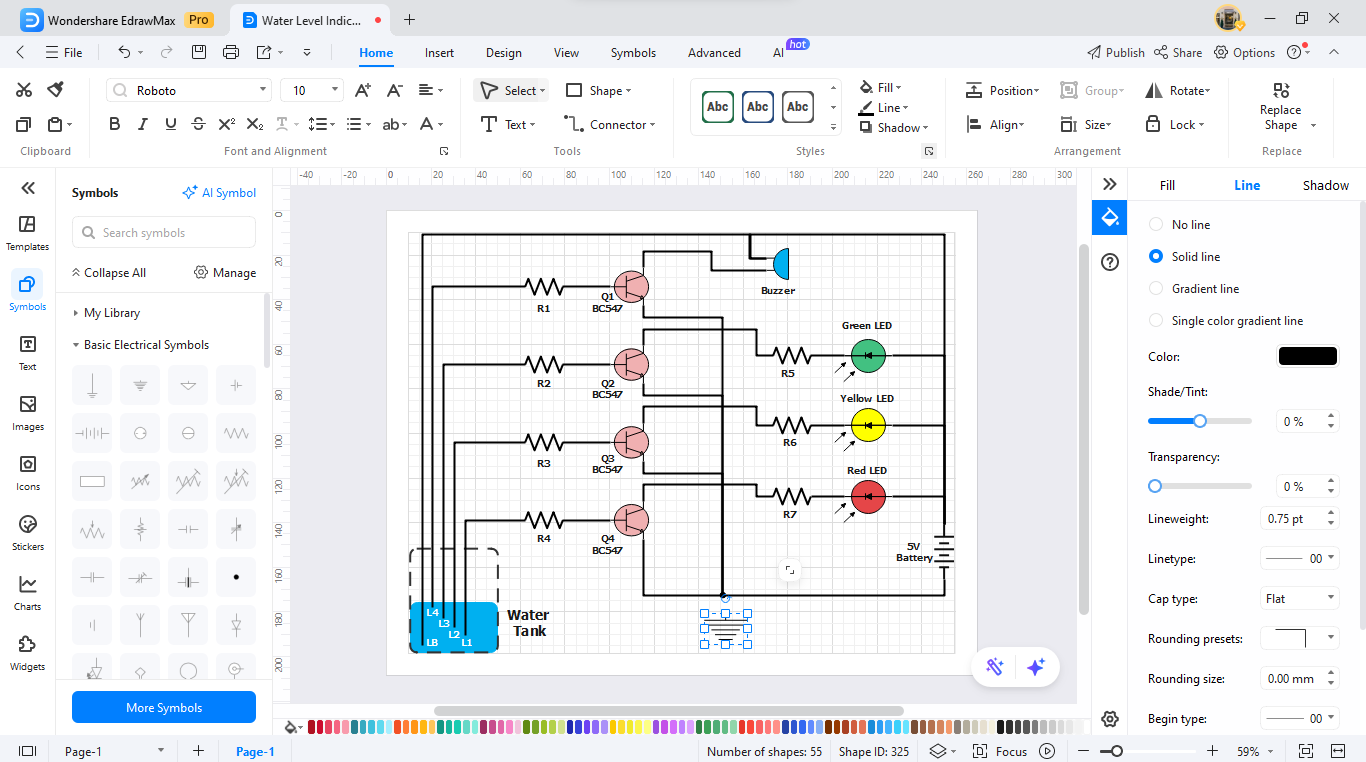
Step 3Add Circuit Symbols
Open the symbol library. Drag the inductor symbols and other circuit elements to your workspace. Adjust the settings of each component to fit your design. Use the drawing tools to connect the elements with lines or wires. EdrawMax’s smart connectors ensure precise alignment and connection of components.
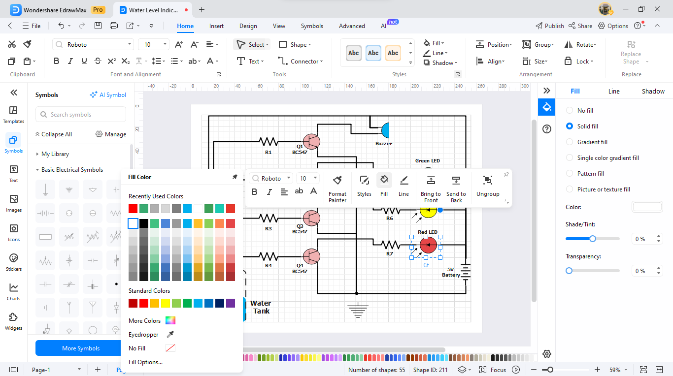
Step 4Arrange and Customize
Add labels, annotations, or dimensions to your design for clarity. Use formatting tools to enhance the diagram's appearance.
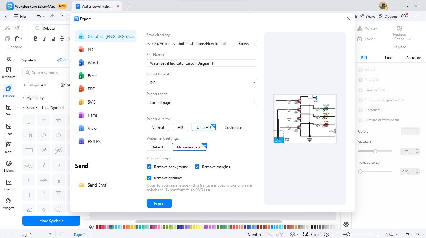
Step 5Review and Export
When done, click "Export" to save your diagram in a format like PDF, PNG, or Visio for easy sharing or printing.
Ending Notes
Inductor symbols are key in circuit design and electrical engineering. They simplify reading schematics and improve communication in technical drawings. Each symbol, from air-core to shielded inductors, represents a unique component with a specific function. This clarity helps engineers and designers create efficient and precise circuits.
Explore EdrawMax, a comprehensive visual collaboration platform, to enhance your skills further. It has over 26,000 symbols, including many inductor symbols. EdrawMax allows you to create professional circuit diagrams easily. Its features make it great for beginners and pros, and its cross-platform compatibility adds value.
Explore EdrawMax and discover limitless options for your designs. Enjoy simple diagram creation that takes your projects further. Try EdrawMax today!
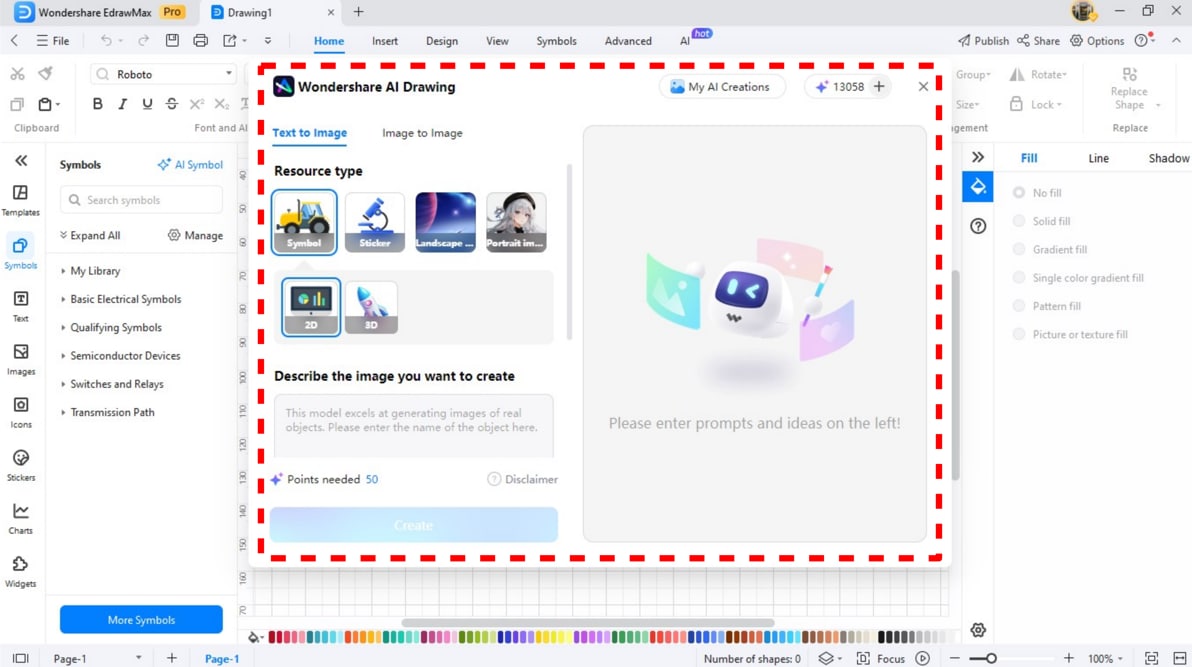
AI Diagram Generator
Enter your prompt. Upload files if needed. Generate diagrams, charts, or slides instantly.


