


Integrated Circuit Symbols are the essential element in circuit schematics. In electrical and electronics engineering, these circuit diagram symbols form a universal language. They enable professionals to interpret, analyze, and troubleshoot circuits with accuracy.
Understanding these symbols is crucial for project design and documentation. This article looks at common integrated circuit symbols. It explains what they do and how users use them in electrical schematics.
In this article
All Common Types of Integrated Circuit Symbols
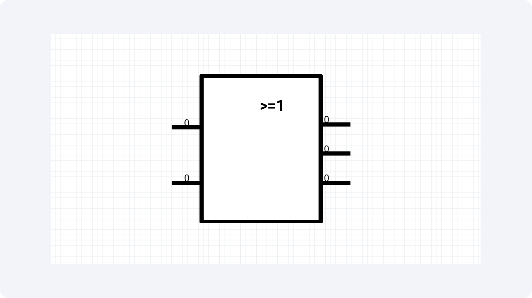
Logic Gate IC
Logic Gate ICs are key components in digital electronic systems. They have integrated circuits that do basic Boolean functions like AND, OR, NOT, NAND, NOR, XOR, and XNOR. In schematic drawings, these components appear as rectangular boxes. Input signals come in from the left, while output signals go out on the right.
Logic gate ICs handle tasks in computing, input processing, and system control. Each has distinct electrical properties for various applications.
Operational Amplifier
A triangular symbol represents an operational amplifier. Its left side has inverting (-) and non-inverting (+) inputs that connect to the output on the right. This versatile analog IC provides high voltage amplification. It works with infinite input resistance and zero output resistance under ideal conditions.
Analog designs use op-amps to build various circuits. Operational amplifiers play key roles in instrumentation and analog computing. They perform essential mathematical computations.

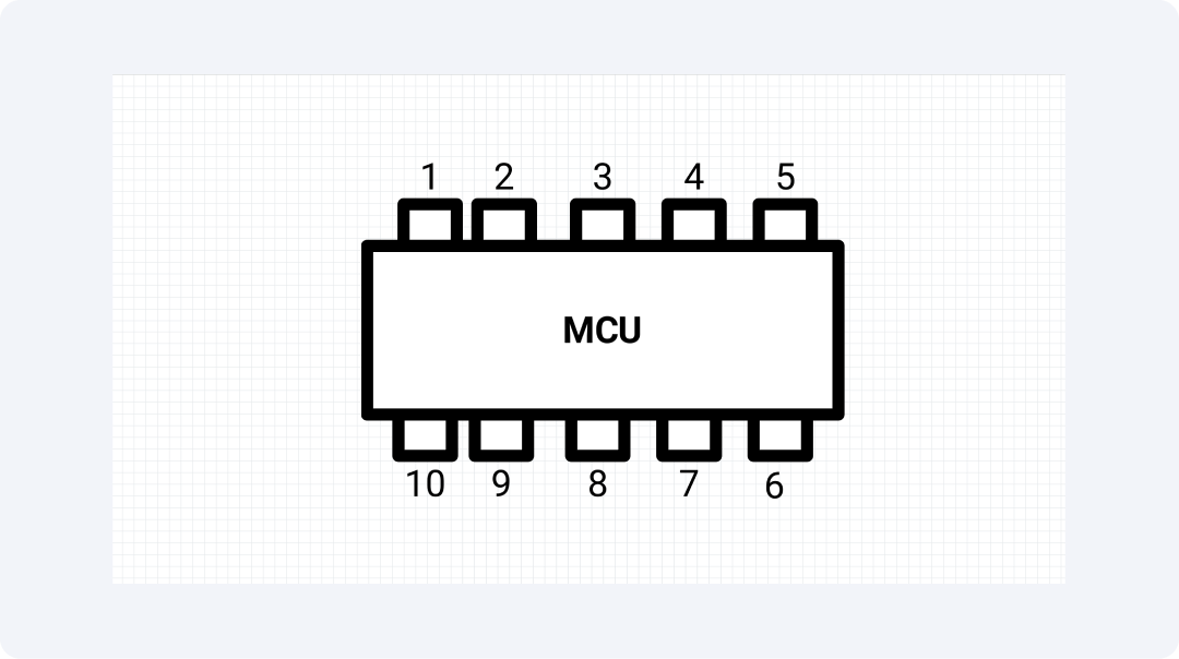
Microcontroller
Microcontroller symbols show a rectangular shape. They have many pins for power, grounding, and input/output ports. They also include different interface sections. Integrated circuits create strong electronic blocks.
Every electronic system uses microcontrollers, especially in industrial automation and consumer devices. These microcontrollers have programmable features. You can find them in consumer devices, car controls, medical products, and communication systems.
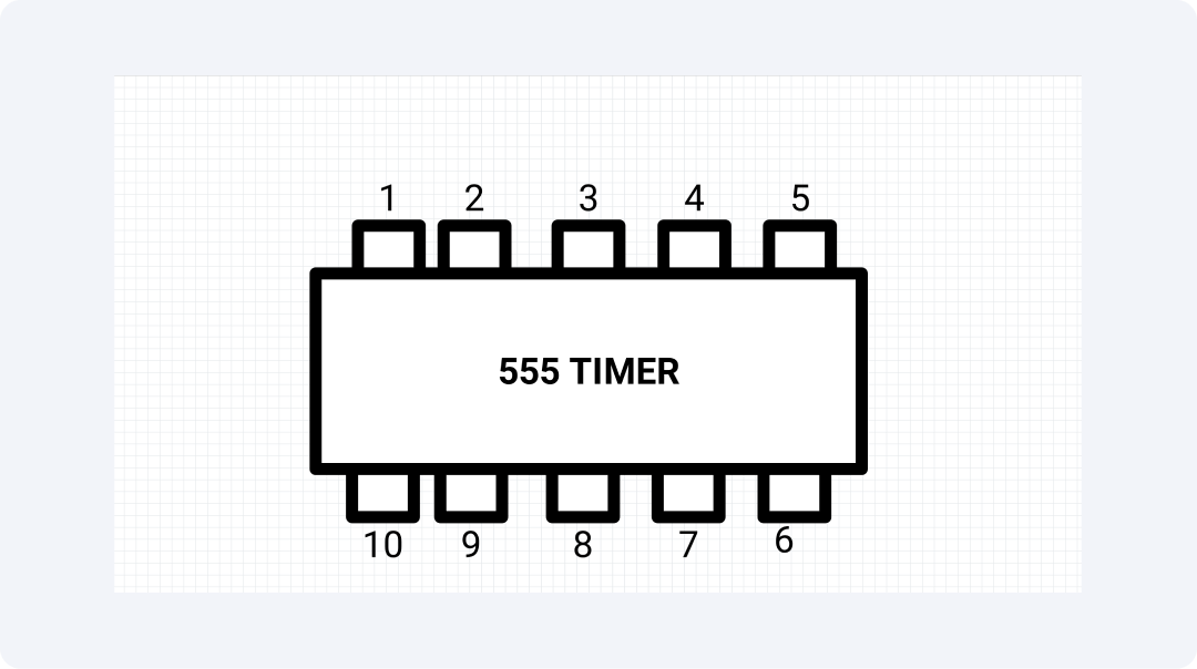
Timer IC
A rectangular block represents the 555 Timer IC. It has eight connectors: trigger, threshold, output, and reset inputs. The 555 timer creates time delays and waveform oscillations. It helps generate pulses, control LED flippers, manage PWM, and run timing sequences. After its launch, this IC became one of the most popular choices in electronic design.
The simple design, reliable operation, and adaptable features contribute to its widespread use.
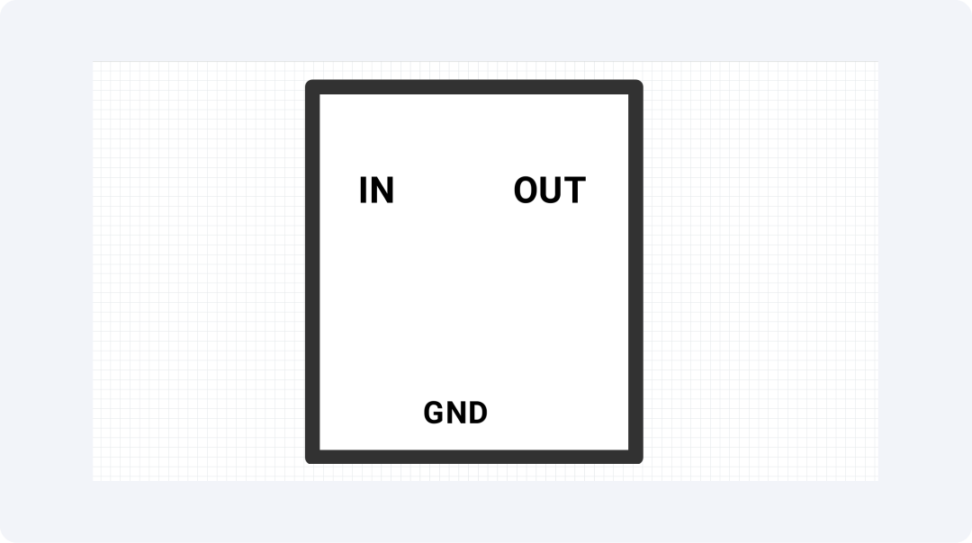
Voltage Regulator
The Voltage Regulator IC has a rectangular shape. It features input terminals, output connections, and a ground connection. Changes in raw inputs or outputs do not impact this device. It regulates voltage to ensure stable power for sensitive electronic systems.
Voltage regulators are key components. They ensure stable power supply designs and support battery-powered devices. They also provide stable reference voltages to connected systems.
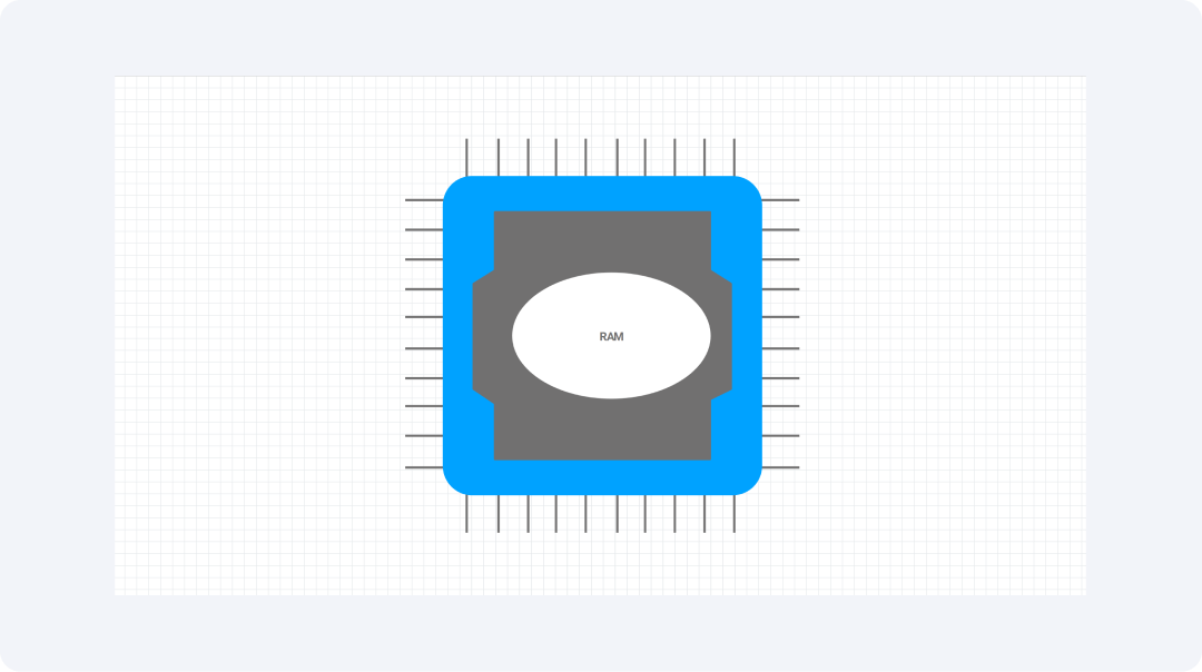
Memory IC
The memory IC has three parts shown in rectangular boxes. These include address inputs, data lines, and control signals. Memory components offer digital storage using ROM, RAM, EEPROM, and Flash memory.
Memory ICs store digital information. They support both microcontroller programs and user data storage. They excel based on three main factors: how much they can store, how fast they access data, and how well they resist damage.
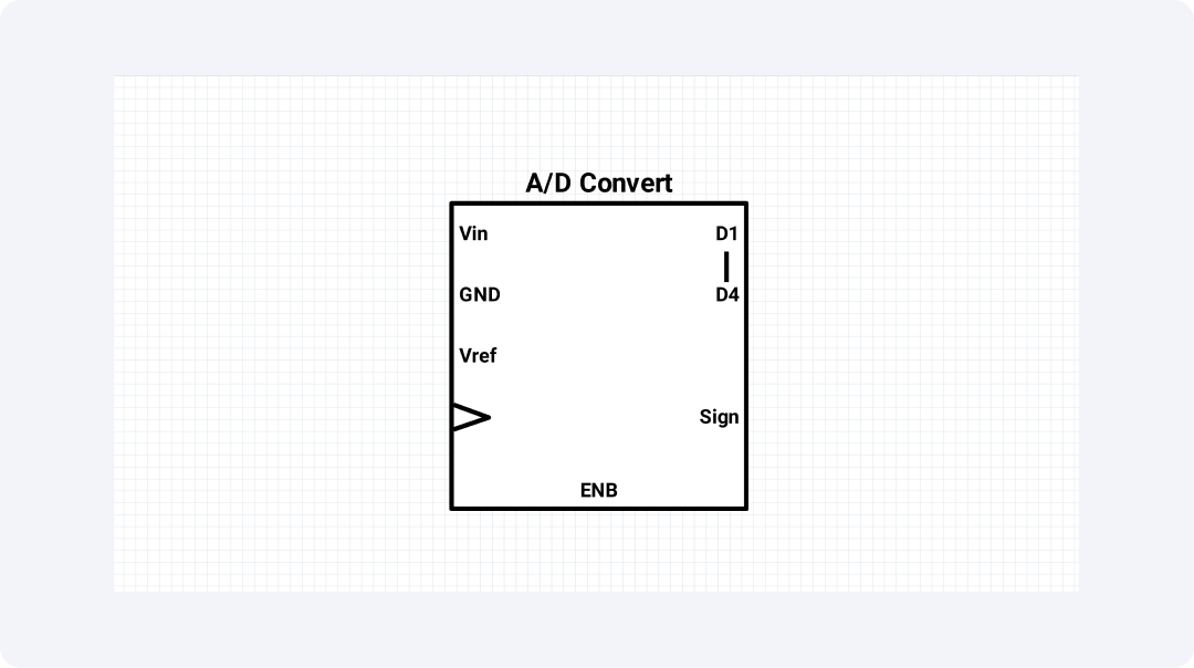
Analog-to-Digital Converter
The ADC symbol has two sides. These show analog inputs connected to digital outputs in a rectangular shape. ADCs are special IC devices that change continuous analog signals into exact digital values. This allows microprocessors and digital systems to work with analog environments.
The Analog-to-Digital Converter (ADC) connects physical sensor data to digital processing. Its performance relies on factors like bit count, conversion speed, and accuracy. These factors determine if an ADC will work with digital multimeters, audio recorders, and industrial data acquisition tools.
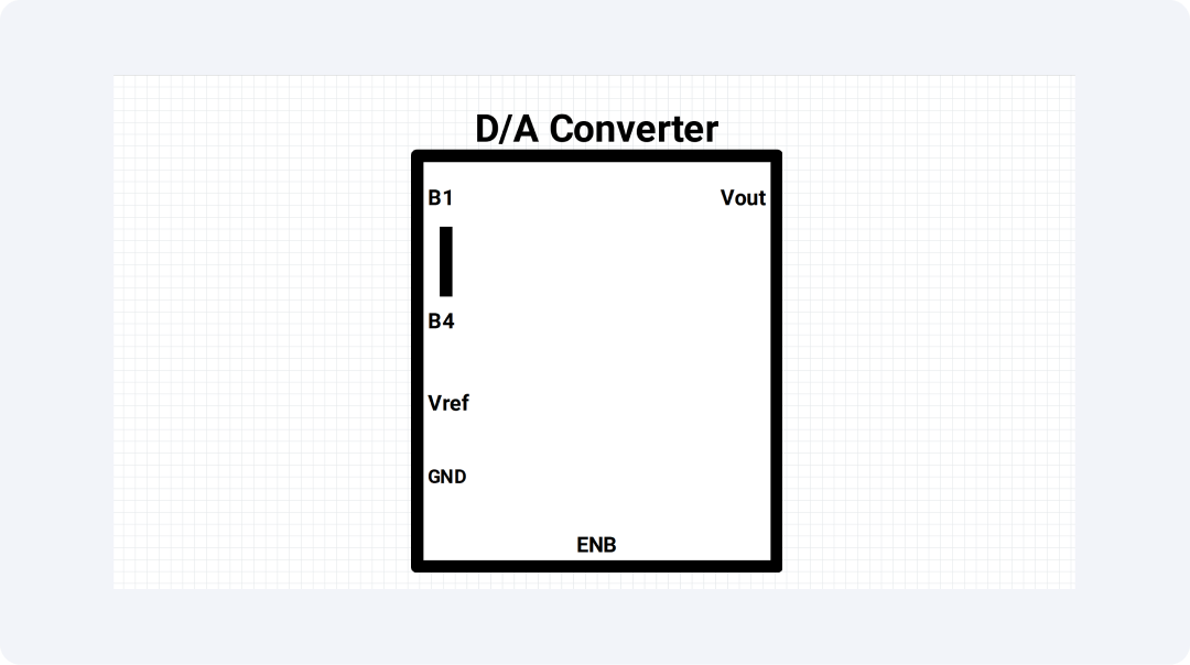
Digital-to-Analog Converter
The electronic schematic of a DAC shows the same symbolic components as an ADC. However, it has analog outputs and digital inputs. Digital codes are changed into analog voltage or current levels. This lets digital systems control analog devices that provide continuous output signals.
Digital-to-analog converters allow digital control of analog processes. This is important for audio playback, test equipment, motor controls, and signal generators. The DAC system works best when three factors are strong: resolution, settling time, and linearity across its output range.
Power Amplifier
Power Amplifier ICs have a rectangular shape. They include input and output points, a power supply, and control pins. These parts increase signal strength. They help run speakers, motors, and transmission lines without adding noise.
These amplifiers boost weak signals. They work well for audio systems, RF communications, motor drivers, and industrial control systems. A power amplifier IC works best when you consider its power handling, efficiency, bandwidth, and distortion levels.
Multiplexer
The Multiplexer symbol lets many inputs connect to fewer outputs. It uses control lines to select which input to use. These digital switching ICs use one input channel. They can route many signals or send one signal to different places.
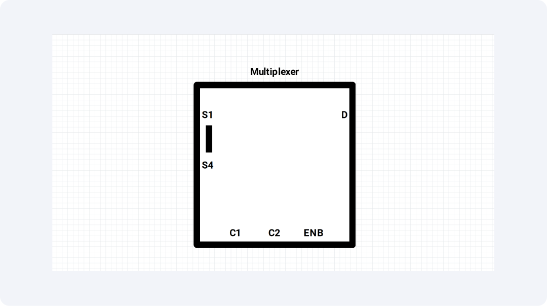
These components simplify signal routing and lower the pin count in designs with limited space. They are key for sending data and processing signals. They also expand input output connections in microcontrollers and digital systems.
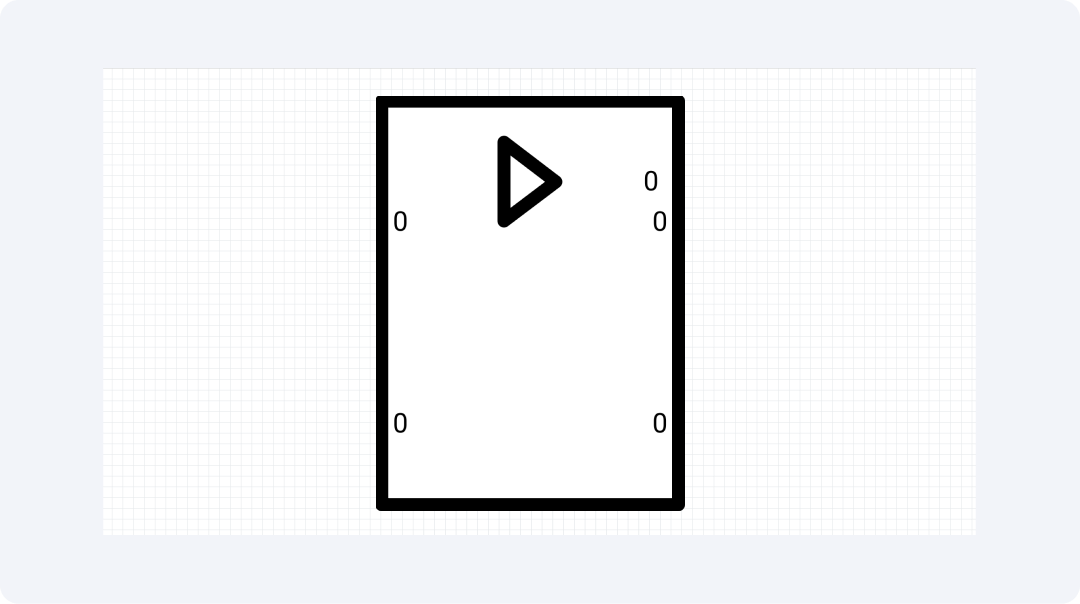
Oscillator IC
Oscillator IC symbols show a circle with frequency control (~). These components create periodic signals at specific frequencies. They act as timing references and carrier signals for digital systems and communication tasks.

Oscillator ICs are stable frequency generators. They support digital systems by ensuring synchronous operations and precise timing. They also aid communication networks.
Explore More Integrated Circuit Symbols on EdrawMax
EdrawMax includes a full library of electronic component symbols. This library has all the key symbols for integrated circuits. Users can access over 26,000 schematic elements. This is part of EdrawMax's diagramming system for accurate electronic design.
What Is EdrawMax?
EdrawMax offers an easy-to-use design environment for creating professional circuit diagrams and schematics. This app helps engineers, students, and electronics enthusiasts create detailed technical drawings. It offers a wide range of features.
- Extensive collection of 26,000+ electronic symbols for circuit design
- User-friendly drag-and-drop interface for seamless diagram creation
- The program has different templates you can edit to speed up your project development.
- Cross-platform compatibility across Windows, macOS, and Linux
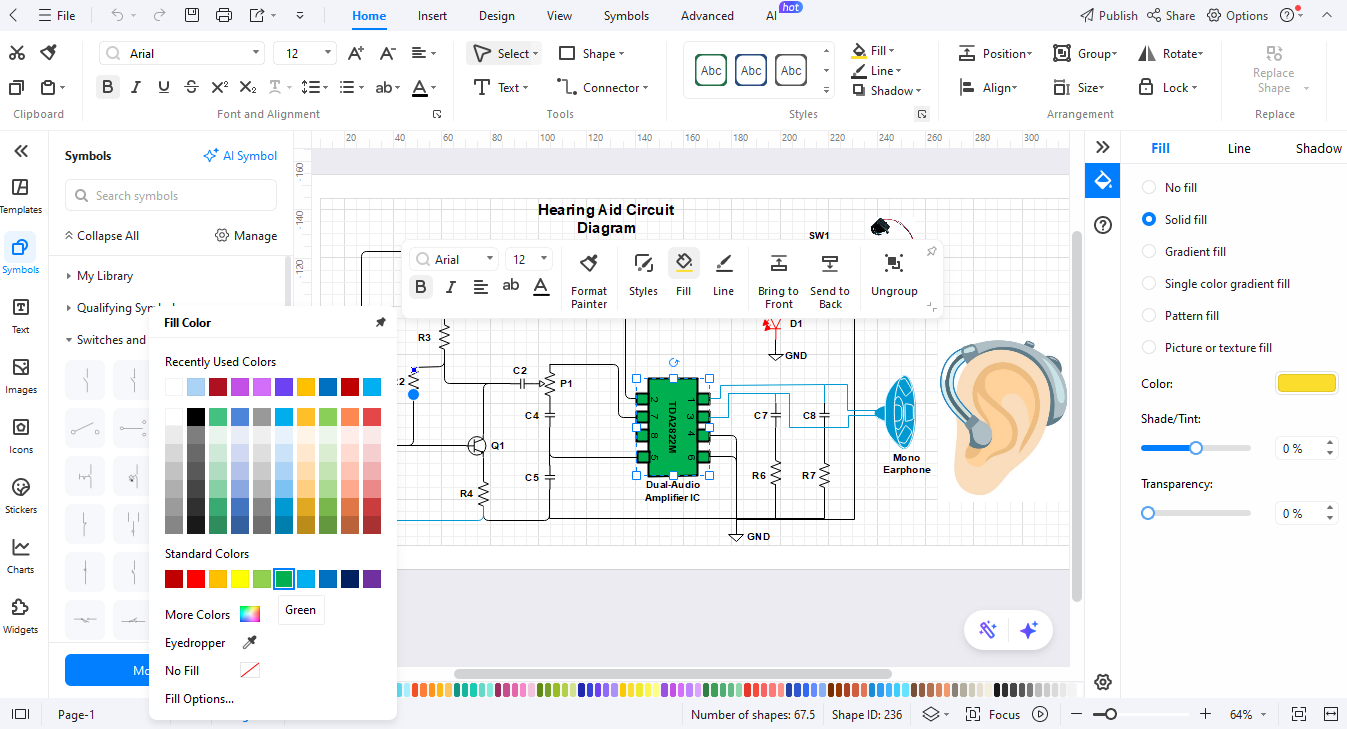
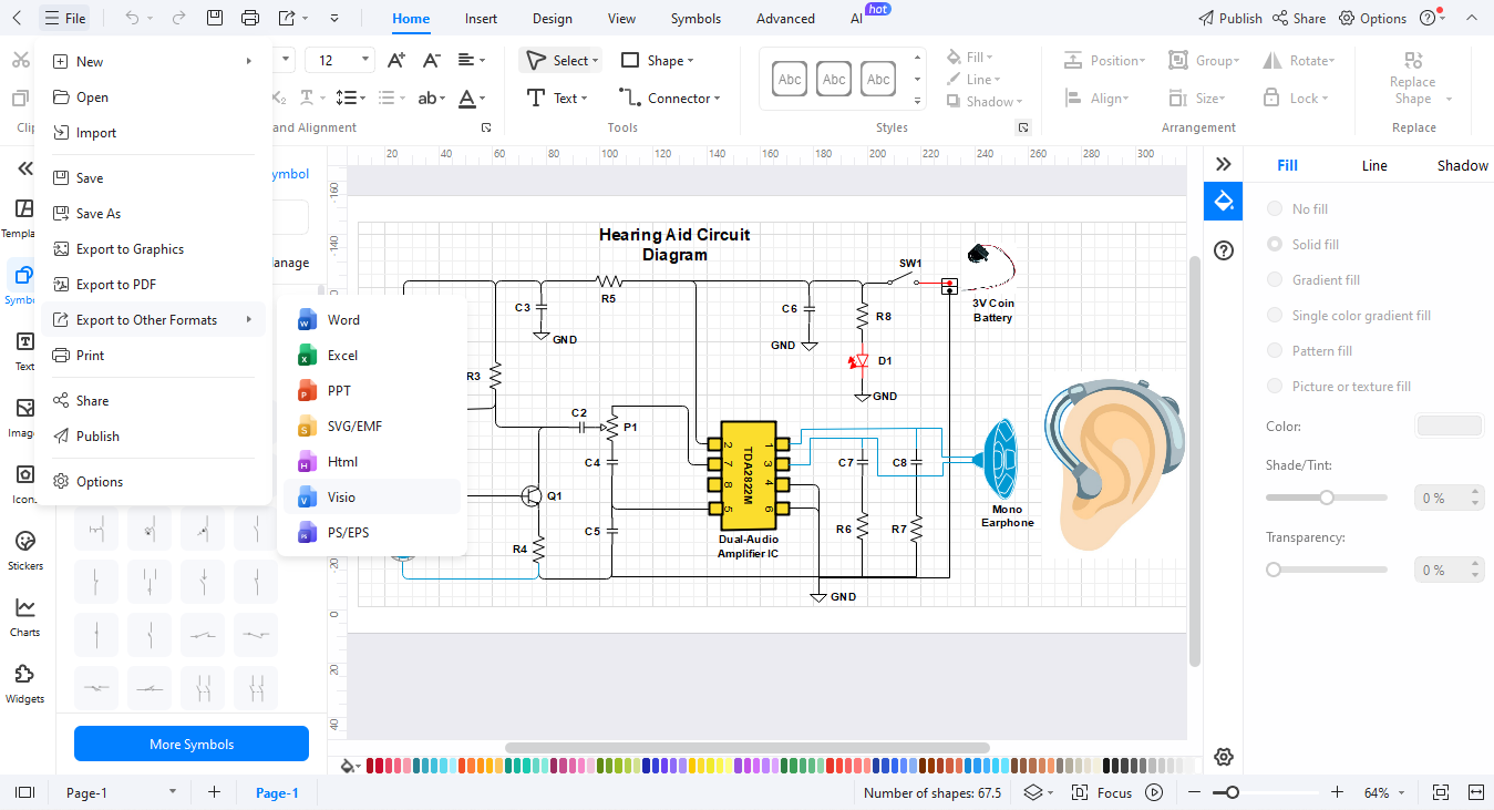
- The platform supports file export through PNG, PDF, and SVG formats.
How to Find More Symbols on EdrawMax?
Finding the right symbols in EdrawMax is a straightforward process. Let’s break it down into simple steps:
Step 1Open EdrawMax and Login
Launch the application first and then log in using your desired authentication method.

Step 2Start a New Diagram
Select the "New" option and then choose "Blank Diagram" to create your new workspace.

Step 3Access the Symbol Library
The left menu has the Symbols panel. You can use it to explore EdrawMax's large symbol library.
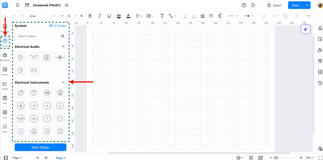
Step 4Search for Specific Symbols
Use the search bar to locate integrated circuit symbols by name or function.
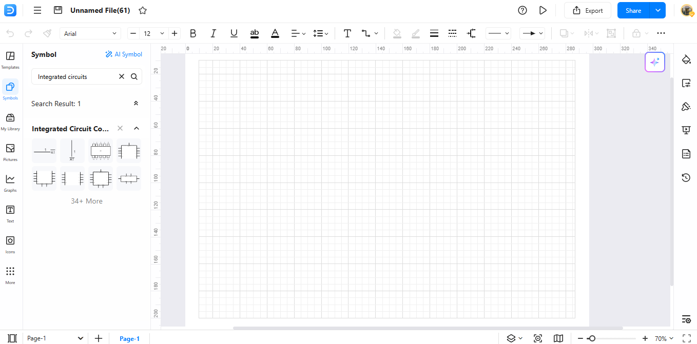
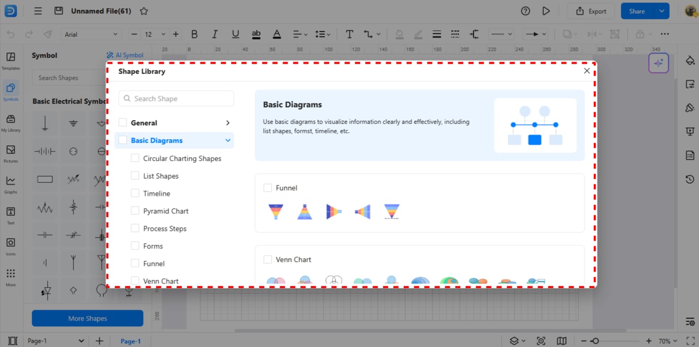
Step 5Download Additional Symbols
To add more symbol packs, go to the bottom section, and click on more symbols from the menu.
Step 6Make Your Custom Symbols
Right-click on new symbols to begin their customization. Right-click your diagram and choose "Add to Library." This lets you use it in future diagrams.

How to Make a Circuit Diagram on EdrawMax
Creating a circuit diagram with frequency dividers is a breeze in EdrawMax.
Step 01Open EdrawMax
Open the EdrawMax online tool on your browser.

Step 2Create a New Project
Start a new diagram using the “New Diagram” from the options. You can start your design from an existing template or a new blank one.

Step 03Add Circuit Symbols
Search for the symbols in the library section. Insert the required circuit elements in your diagram.
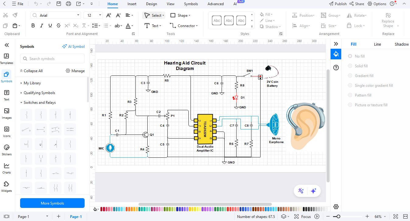
Step 04Customize Your Diagram
Use the connection tools to create wires between components to make correct connections. Add labels for clarity.
Step 05Export the Diagram
Once finished, review your diagram. When you're satisfied, click the “Export” button. You can save your diagram as a PNG, PDF, or SVG file.
Ending Notes
Integrated circuit symbols are vital for electronic designers and enthusiasts. These standardized drawings simplify complex circuit information, making it easier to communicate functionalities. With EdrawMax, anyone can create professional diagrams. The design tools are easy to use for both beginners and experts.
EdrawMax features a large symbol library and a user-friendly interface. This helps users create accurate IC diagrams, no matter the complexity. Use EdrawMax to transform your ideas into expert schematics in a short time.
AI Diagram Generator
Enter your prompt. Upload files if needed. Generate diagrams, charts, or slides instantly.


