


Logic gate symbols are the essential element of a digital circuit. These circuit diagrams use standard logic gate symbols. They show logical operations with clarity and precision. Engineers rely on these symbols for digital circuit design, trouble shooting, and analysis.
Understanding these universal symbols is key when working with electronic systems. This article explores the various logic gate symbols, how they're represented, and why they matter in circuit diagrams. Digital circuit design needs you to master these symbols for creating efficient and reliable systems.
In this article
All Common Types of Logic Gate Symbols
AND Gate
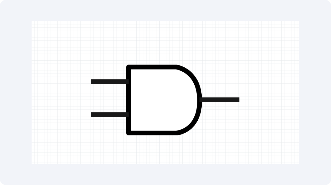
The AND gate symbol is represented by a flat D shape where the left side remains straight. The symbol demonstrates the logical conjunction functionality. The symbolic representation does not illustrate the internal operation of the gate. The symbol depicts logical functions instead of component attributes.
Signals enter the device through flat lines and leave through curved lines. This symbol serves as one of the basic elements for designing digital logic diagrams. The AND gate is a key part of digital circuits. It requires multiple conditions to be true at the same time.
3-input AND Gate
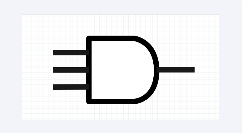
The symbol for a three-input AND gate looks like a standard AND gate, but it has three input lines instead of two. For the output signal to activate, all inputs must be HIGH (1). This design allows the gate to handle complex logical expressions in one unit.
The added input gives the gate more versatility. It can perform advanced logical functions without needing extra hardware. The three-input AND gate is key in circuits. It controls multiple activations before performing a task.
OR Gate
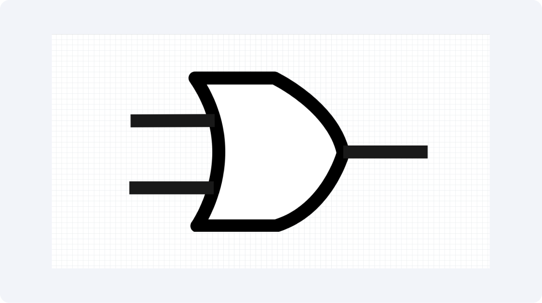
The OR gate symbol features curved inputs that meet at one output point. It represents logical disjunction, assisting users in distinguishing it from the AND gate symbol. In digital systems, OR gates are crucial. They activate actions when any of several input conditions trigger.
The unique shape of the OR gate symbol helps engineers spot these gates in complex circuits. This design makes it easier for them to understand the logical structure of digital circuits.
3-input OR Gate
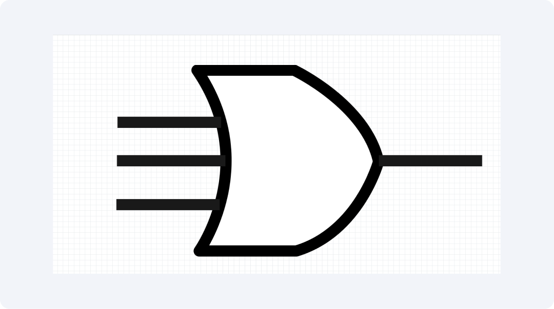
The symbol for a 3-input OR gate has the familiar curved shape of regular OR gates. It features three entry lines. The symbol shows three input signals, where only one value is needed to activate the output. This extra input lets the gate do complex logical tasks without needing extra hardware.
The 3-input OR gate is useful in alarm or notification systems. It activates whenever any of the triggering events occur. The 3-input OR gate's visual shows a logic operation. It evaluates several signals and only needs one active input to create an output.
NOT Gate

A small circle appears at the output of the triangle-shaped symbol that represents the NOT gate (inverter). This circle shows that an inversion operation affects the signal inputs. The circle indicates inversion in logic gates and is a constant feature in all inversion logic gate diagrams.
The NOT gate creates complementary signals. Its shape makes it easy to identify in complex circuits. The NOT gate also works with other gates to build advanced logical operations.
NAND Gate
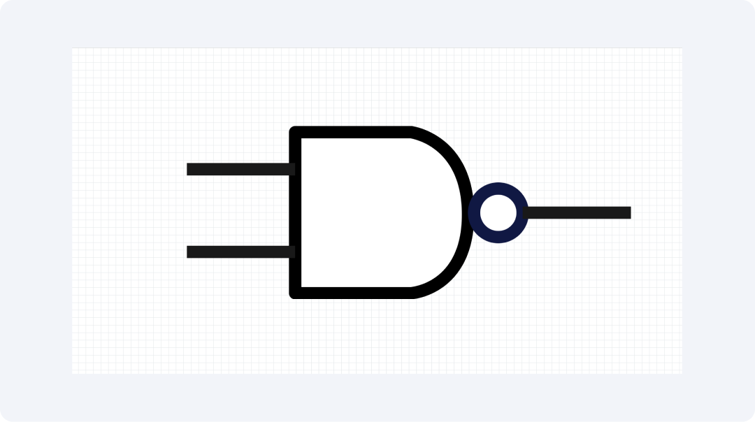
The NAND gate symbol combines the AND gate with a circle at the output. It performs an AND operation and then flips the output to NOT. Each NAND gate symbol has a small circle for a consistent appearance. NAND gates are versatile. They can perform any logical operation.
They are widely used in circuits because they are simple and flexible. A single NAND gate symbol clearly shows the combination of AND logic and inversion.
NOR Gate

A NOR gate symbol looks like an OR gate but with a small circle at the output. This circle indicates that the output is inverted. NOR gates provide the same functional completeness as NAND gates. This means they can perform all logical functions.
The NOR gate symbol includes everything needed for OR functionality and inversion. This clear representation helps engineers gain a better understanding of circuit behaviour.
XOR Gate
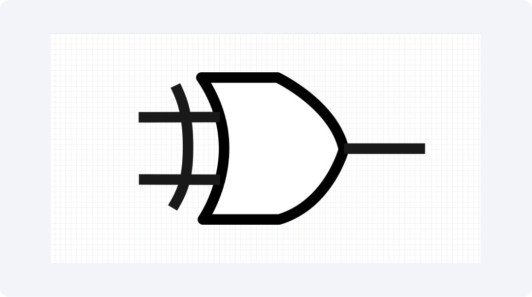
The XOR gate symbol has a curved line by its input, along with features of the standard OR gate. This symbol represents an exclusive OR gate. The curved line helps to set the XOR gate apart from the basic OR gate symbol.
XOR gates are used in arithmetic circuits specifically for addition operations. The XOR plays an important role in error detection systems and parity checking. The unique design of this symbol allows engineers to identify special functions in complex digital designs quickly.
XNOR Gate
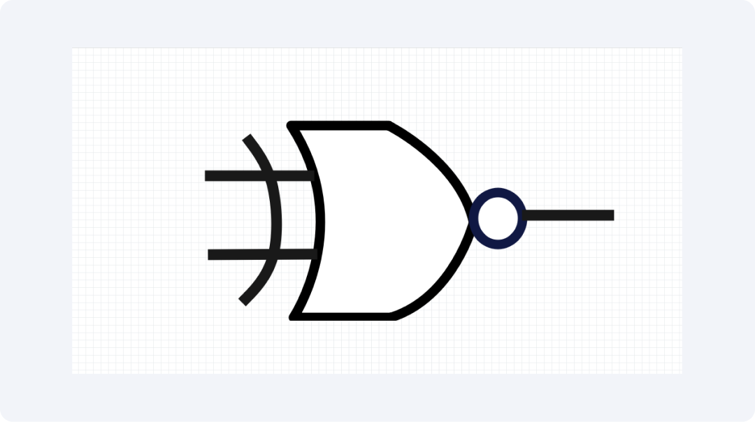
An XNOR gate symbol looks like an XOR gate but has a small circle at the output. The curved line and output circle help clarify the gate's function. Comparator circuits and equality detection solutions use XNOR gates for their unique purposes.
This gate is a simple way to see when two signals match exactly. Engineers easily understand the function using XNOR gate symbols.
Explore More Logic Gate Symbols on EdrawMax
Discover a wide variety of logic gate symbols in EdrawMax's libraries. This visual collaboration app has more than 26,000 symbols available. The collection features electronic symbols across many categories. Users can find all the components they need for circuit design on this platform.
What Is EdrawMax?
EdrawMax offers users a friendly visual interface. The software does more than just create diagrams. It allows users to make various diagrams, charts, and visual components. EdrawMax is suitable for all skill levels, thanks to its flexible design. It truly covers all needs. Users can access detailed engineering schematics, helpful workflow plans, and student presentations.
Key Features:
- Users can choose from over 26,000 symbols to create different types of diagrams.
- The system has a drag-and-drop interface for easy operation. This makes the design process straightforward.
- Users can start their projects using many editable templates provided by the software.
- The software works seamlessly on all devices like Windows, macOS, and Linux.
- Users can save their designs in any desired format including PNG, PDF, SVG, and more.
How to Find More Symbols on EdrawMax?
Step 1Launch EdrawMax
Start by launching EdrawMax and logging in.
Embark on your dream home journey. Explore the artistry of modern living in these 10 simple two-floor house plans, where simplicity meets elegance. The designs are from Wondershare EdrawMax ’s vibrant Templates Community.
All templates below are free to access, view, and edit. You can download the template or the upgraded version for free as well.
Step 2Create a New Project

Click the New tab in the interface. Select "Blank Diagram" to create a new project workspace.
Step 3Access the Symbol Library
Use the left menu panel to access symbols. Tap the Symbols panel to explore EdrawMax's wide range of symbols. Each diagram type has its unique symbols in the collection.
Step 4Search for Specific Symbols
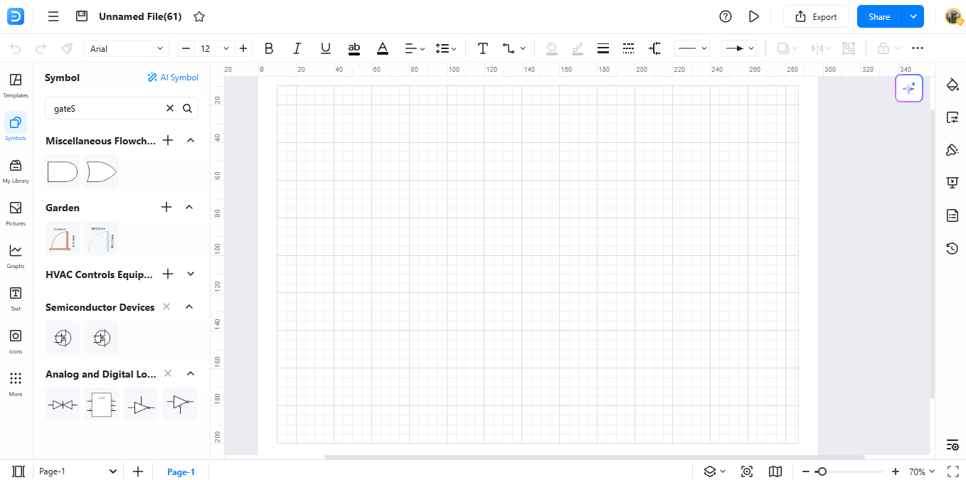
Find the required symbol by typing its name in the search bar present at the top of the workspace.
Step 5Download Additional Symbols

Click "More Symbols" at the bottom to view the symbol collection. Access downloadable symbol packs through the drop-down menu. Select the packs you want from the list. After saving, they will appear in your custom library.
Step 6Create Custom Symbols
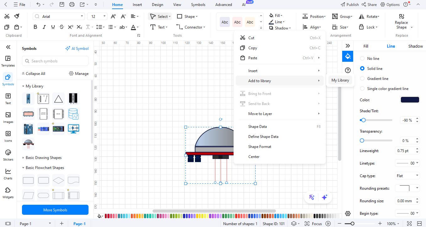
Build personalized symbols using EdrawMax's simple tools. To design your own, right-click a new symbol in the collection. Choose "Add to Library" to save your new diagram components.
How to Make a Circuit Diagram on EdrawMax
Step 01Open EdrawMax

Open EdrawMax. Then, choose the "Electrical Engineering" section. You can start your design from an existing digital logic template or a new blank one.
Step 02Create a New Project

In the interface, click "New." Start your workspace by selecting "Blank Diagram" or a "Template" from the options.
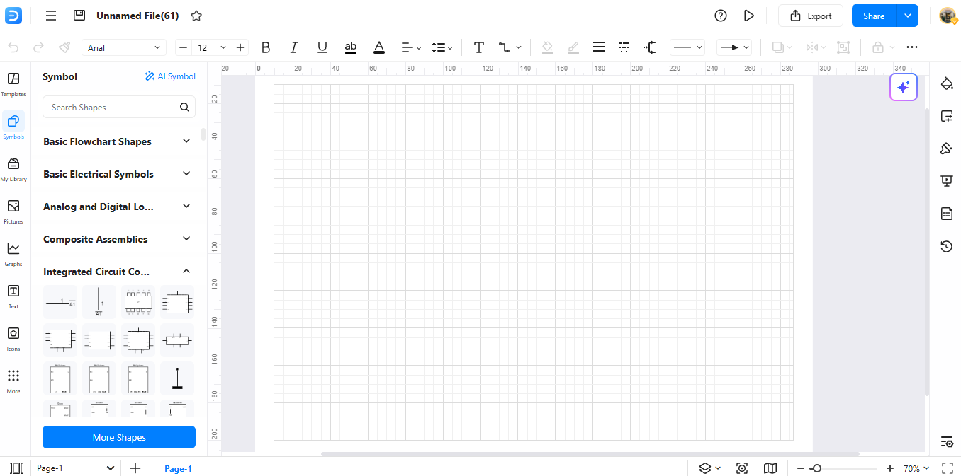
Step 03Add Symbols

Select the Symbol Library from the tools. Drag and drop the needed components into your workspace.
Step 04Customize Your Diagram
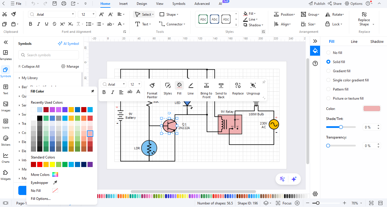
Add descriptive labels to your diagram. Use written information for better understanding. Apply formatting options to enhance its appearance.
Step 05Export the Diagram
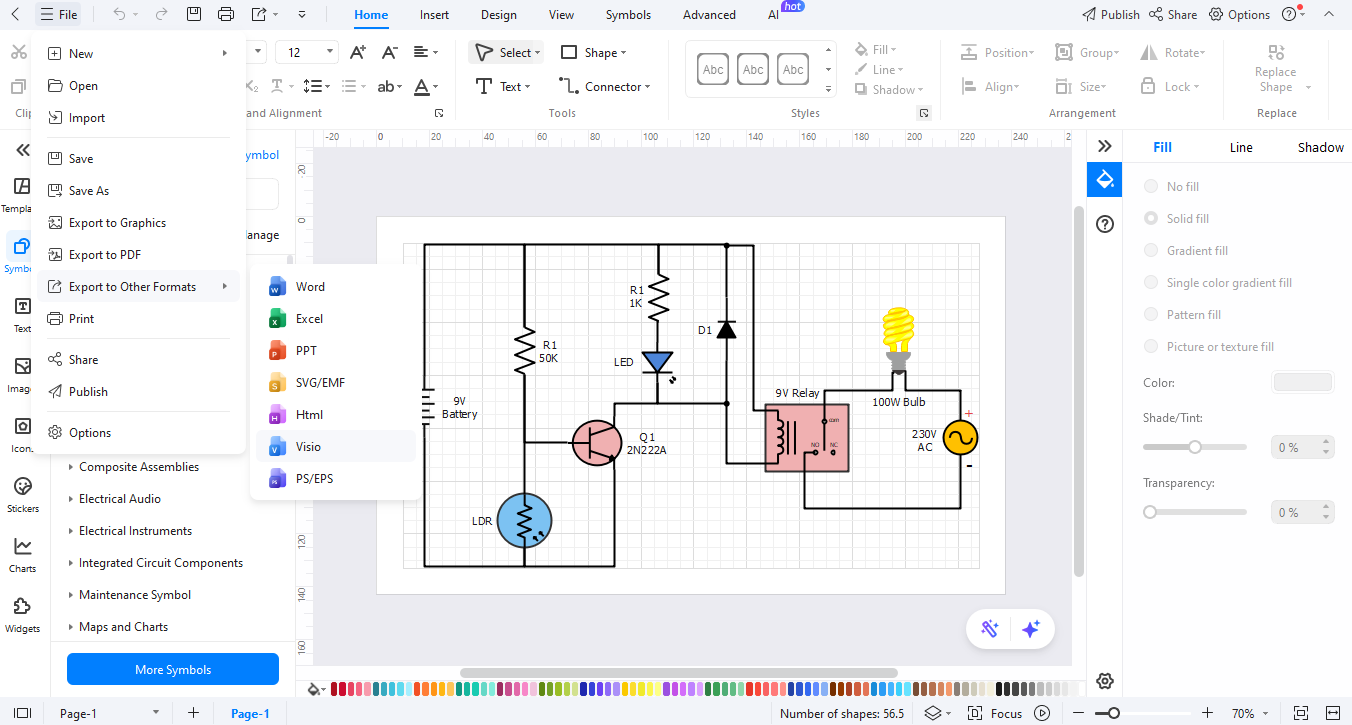
Once finished, review your diagram. Click "Export" in the tools menu to save your design as a PDF, PNG, or Visio file.
Ending Notes
Understanding logic gate symbols is vital for anyone in digital circuit design and electronics. Knowing these symbols and their functions is essential. They visually represent digital operations accurately. Engineers who know logic gate symbols can build better circuits and make diagnostics easier. Recognizing the various symbols is crucial.
You can simplify diagram creation by using EdrawMax for your projects. It has over 26,000 symbols, including all standard logic gate symbols. It lets you drag and drop elements while using smart connectors easily. EdrawMax is easy to use. This makes it easy for anyone, regardless of skill level, to create complex digital circuit diagrams.
AI Diagram Generator
Enter your prompt. Upload files if needed. Generate diagrams, charts, or slides instantly.


