


Digital circuits consist of NAND gates as their foundational construction blocks. The operation of NAND gates produces opposite results when given AND inputs. The gate generates misleading outputs whenever all its provided inputs produce truthful values. Electronic systems heavily depend on NAND gates for their operation.
To construct quality circuit plans one must understand the symbols used in NAND gate designs. This guide provides definitions as well as operational information about NAND gate symbols. The following article investigates how NAND gates strengthen circuit design quality. And learn to produce circuit diagrams through the symbols by using EdrawMax software.
In this article
All Common Types of NAND Gate Symbols
2-Input NAND Gate
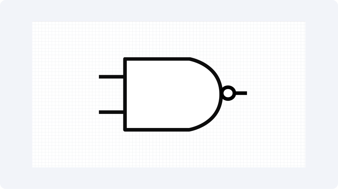
The 2-input NAND gate consists of two input lines and one output line. It operates by providing a "false" output only when both inputs are "true." In every other situation, the output remains "true." This makes it one of the simplest logic gates.
This gate appears in most computer components. It can be made to perform any other logic function if applied properly. The bubble for the output indicates that it reverses or "negates" the AND output. Numerous digital products apply this gate because it requires fewer components to construct.
3-Input NAND Gate
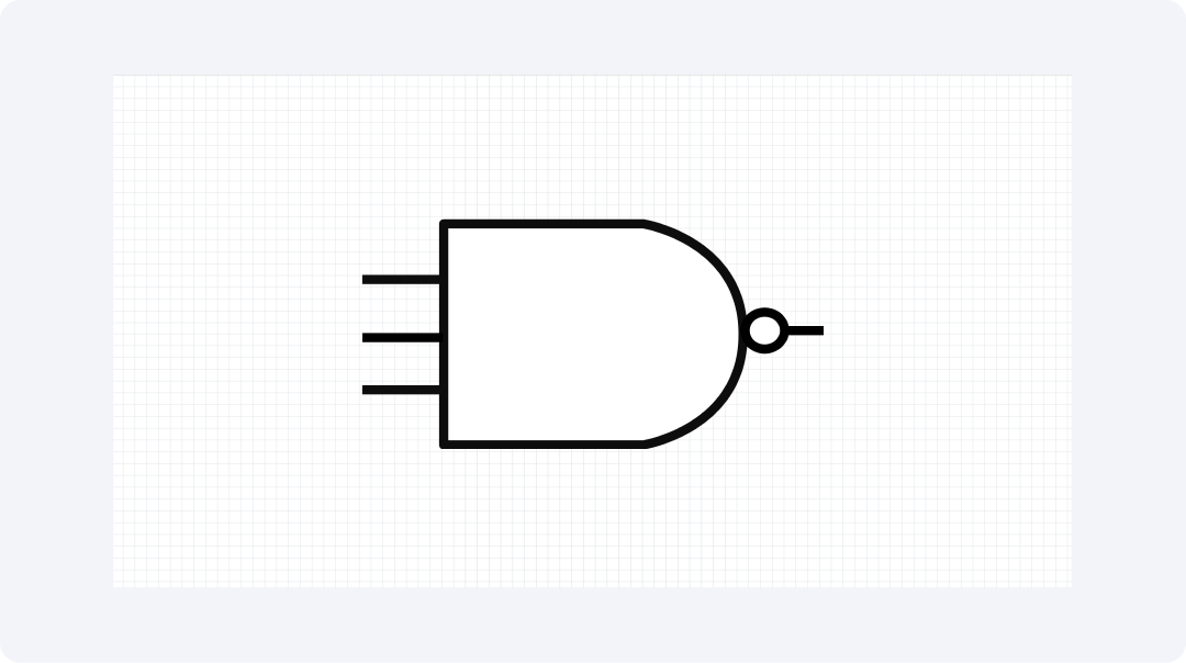
The 3-input NAND gate operates on three input signals simultaneously. It only provides a "false" result if all three inputs are "true." This gate is useful when verifying more than two signals simultaneously. It is appropriate for intricate control systems.
This gate conserves space in chip layouts. It performs the function of three gates within one package. The tiny circle at the output indicates that it inverts the last output. The gate appears frequently in computer number counters and memory components.
4-Input NAND Gate
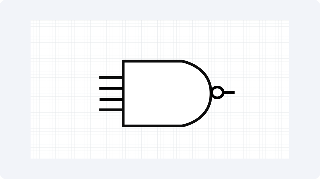
This gate accepts four inputs and produces one output. The output remains "true" unless all four inputs are "true." It then produces a "false" output. It is useful while verifying numerous signals simultaneously in a single gate.
The 4-input NAND gate appears in data verification systems. It is particularly suitable when creating memory components and signal sorters. The gate conserves power and space in chip designs. It also aids in creating timing circuits that have to monitor a lot of signals.
Half Adder
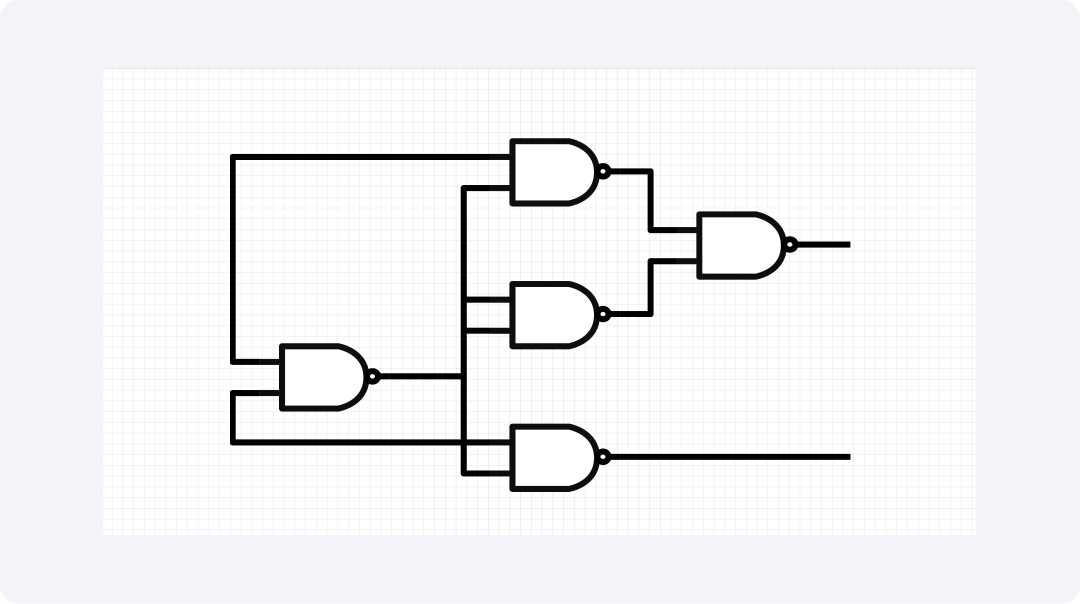
The half adder constructed using NAND gates adds two bits. It provides a sum output as well as a carry output. The design employs NAND gates in an intelligent manner in order to perform calculations using 1s and 0s. It's a simple component for constructing full-adding systems.
This circuit demonstrates how NAND gates can be used to create other functions. It employs gates to determine whether inputs are equal or not. The half-adder is used to construct arithmetic components in computers. It's an important block for constructing number systems to function in digital designs.
NAND IEC

The NAND IEC symbol conforms to the International Electrotechnical Commission guidelines. It has a square shape with the "&" symbol within and a small circle at the output. The type of style ensures that plans are easy to read throughout nations.
Engineers apply this symbol to official plans. It conforms to world standards of circuit drawing. The bubble on the output indicates the NOT function. This symbol facilitates collaboration among teams from various locations on the same project.
Explore More NAND Gate Symbols on EdrawMax
EdrawMax provides you with numerous NAND gate symbols in its symbol libraries. The software contains 26,000+ symbols for circuit components. You can discover any symbol you require for your design projects. This assists students, educators, and makers in drawing precise circuit diagrams.
What Is EdrawMax?
EdrawMax simplifies drawing diagrams. It's easy tools make it easy to construct circuit plans without any issues. The software is suitable for engineers and novices who must produce clear technical images.
Following are some best features that make EdrawMax excellent for design work:
- Offers more than 26,000 symbols for making all kinds of diagrams
- Uses simple drag-and-drop tools that anyone can learn quickly
- Comes with ready-made designs you can change to fit your needs.
- Works on Windows, Mac, and Linux computers without problems.
- Lets you save your work as PNG, PDF, or other common file types
How to Find More Symbols on EdrawMax?
Step 1Start and Sign In
Open EdrawMax on your PC or go to EdrawMax Web. Sign in with Google, Facebook, or Twitter.
Step 2Make a New Project

Click "New" on the main page. Pick "Blank" or use a pre-made plan to start.
Step 3Access the Symbol Library
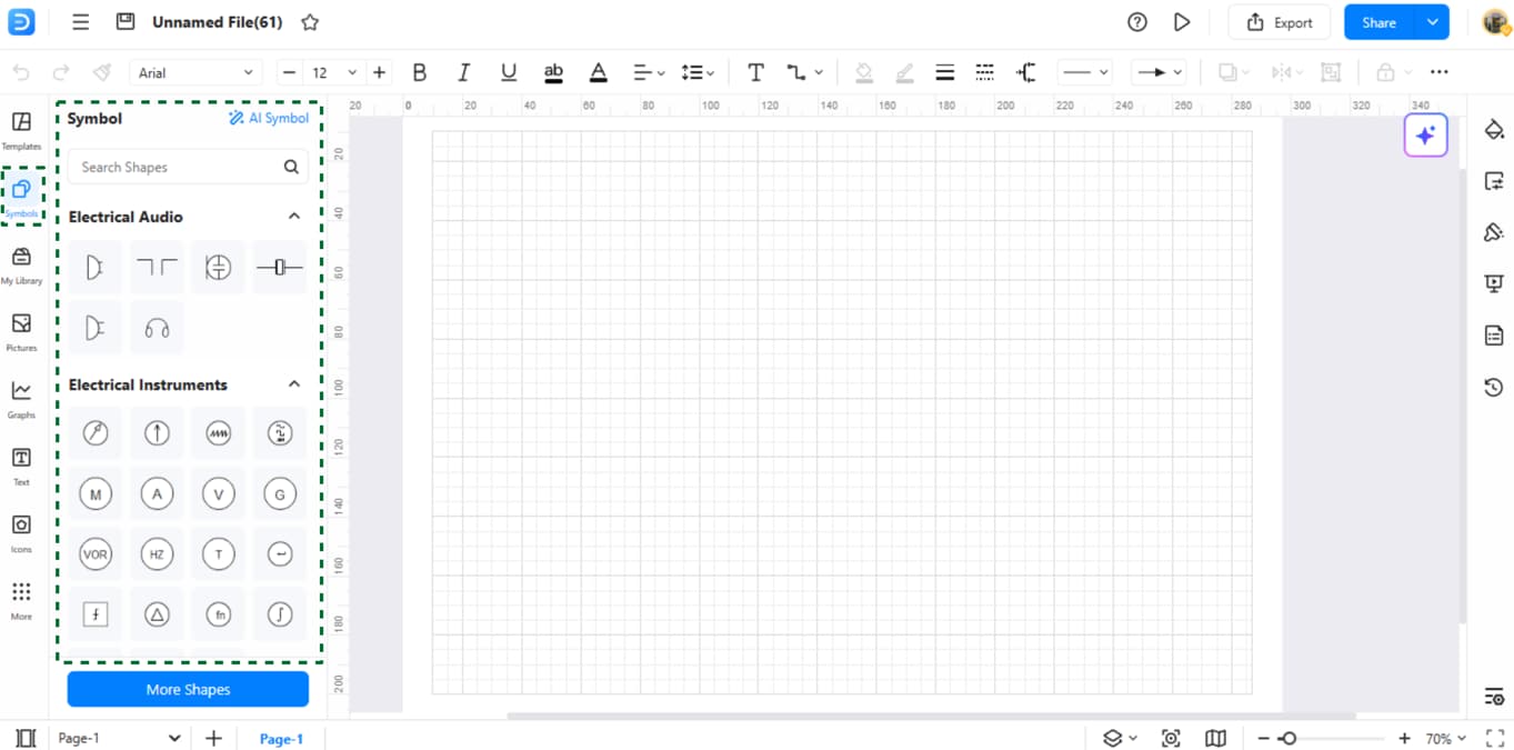
Find the 'Symbols' tab on the left side. Click to see all the kinds you can use.
Step 4Search for Specific Symbols
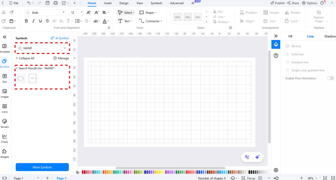
Use the search box at the top of 'Symbols'. Type "NAND" in the search box. This shows just the symbols you need.
Step 5Download Additional Symbols
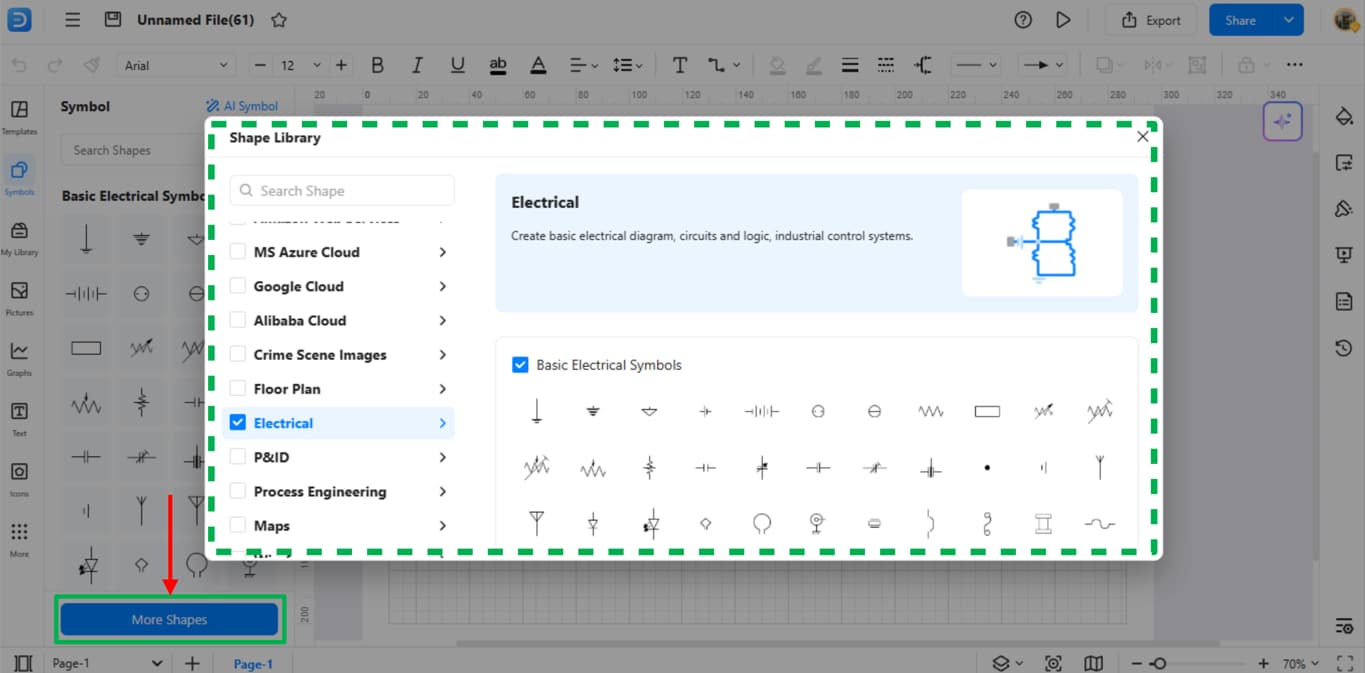
Scroll down in the symbol list to find more packs to add. Pick ones you like to get more choices.
Step 6Make Your Custom Symbols
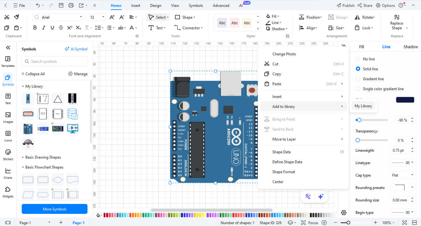
Draw your symbols on the page. Right-click on your drawing and pick "Add to Library" to save your symbols for later.
How to Make a Circuit Diagram on EdrawMax
Making a circuit plan with diodes is easy in EdrawMax.
Step 01Open EdrawMax

Start EdrawMax on your PC or go to EdrawMax Web in your web browser.
Step 2Create a New Project
Click "New" and choose "Circuit Diagram" from the list to start.
Step 03Add Circuit Symbols
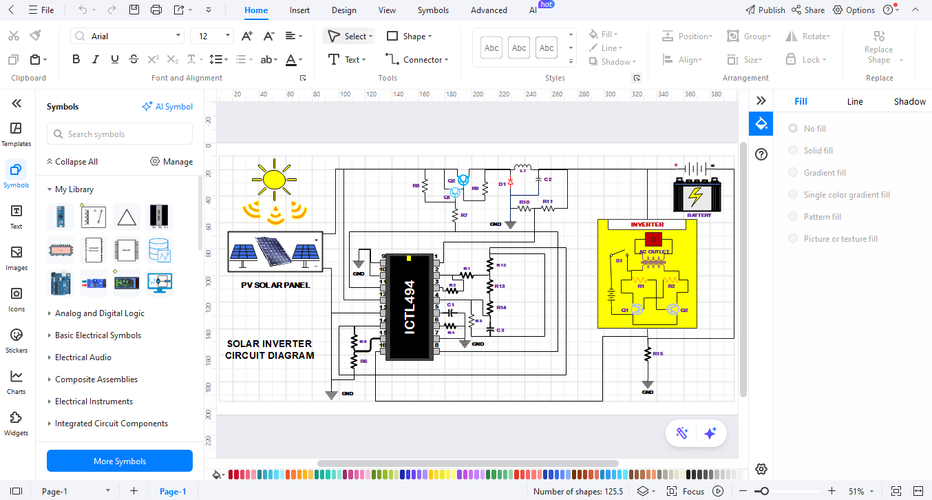
Look through the symbol list for logic gates and other parts. Drag them onto your page where you want them.
Step 04Customize Your Diagram
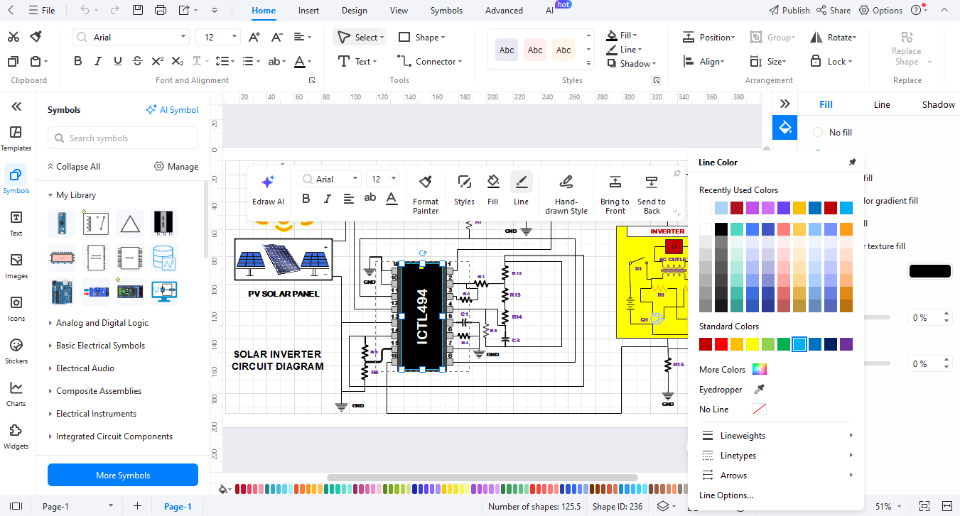
Use the line tools to link parts. Add names and notes to make things clear. Change colors to make it easy to read.
Step 05Export the Diagram

When done, click "Export" to save your work as PNG for the web, PDF for docs, or SVG for sizing.
Ending Notes
By using a NAND gate symbol, digital logic will look easy to everyone. These basic figures represent highly complicated concepts and are easy to understand. EdrawMax spearheads drawing diagrams, for both the professional and the novice. The program contains all the features necessary for you to showcase your ideas clearly and simply.
Try EdrawMax for simplicity in your circuit design. The program helps bring forth wonderful drawings from your neat ideas. Make your own NAND gate circuits today and see how easily you can translate your thinking into pictorial form.
AI Diagram Generator
Enter your prompt. Upload files if needed. Generate diagrams, charts, or slides instantly.


