


NOT gates operate within electronic systems to perform signal inversion between the states of on and off. The compact devices transform elevated signals into lowered signals and diminished signals into elevated signals. NOT gates operate as fundamental components which enable functionality in mobile devices along with automobiles and domestic equipment.
For designing circuit plans it is essential to understand the appearance of the NOT gate marks. The following guide teaches about NOT gate functionality and operational characteristics. EdrawMax enables users to create high-quality circuit plans containing these marks through its user-friendly interface.
In this article
All Common Types of NOT Gate Symbols
NOT Gate
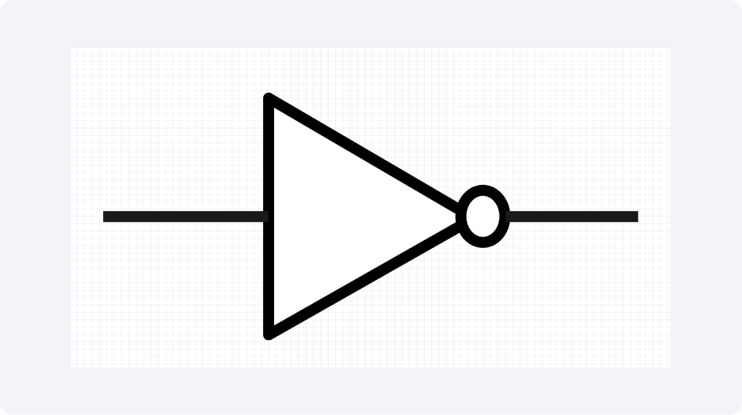
A signal receives an exact inverse output from the NOT gate. High values that enter a device produce low outputs. The system provides an inverted output when the input value is set to low. A circuit signal gets its most fundamental inversion through this method.
A triangle shape with a tiny circular mark at its point represents this device. The simple symbol indicates the point where a signal receives its inversion. Smartwatches and TVs utilize NOT gates as one of their operational components. These gates enable basic on/off operations which appear throughout all everyday tools.
Inverted AND Gate
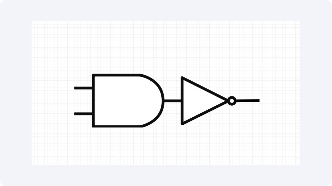
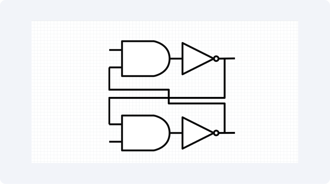
The Inverted AND gate performs a double check for all active inputs before it produces its inverted output. When all inputs are present the output becomes a NAND gate. The gate will produce a low output signal when all input signals achieve high levels. The gate maintains its high state throughout the operating period.
The inverted AND gate appears as an AND gate with an added small circle located at its termination point. NAND gates provide exceptional value since they enable the creation of any other logic gate. NAND gates operate in memory chips while also performing calculations and powering most sections of your phone and computer.
Inverted OR Gate
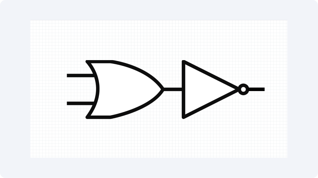
The Inverted OR gate starts by checking if any input is activated before producing an inverted output. This makes a NOR gate. The output remains high only during the specific condition where all input values remain at their lowest levels. Any input signal at high values will maintain the output signal at its low state.
The symbol depicts an OR gate that includes a circular ending. NOR gates alongside NAND gates have the capability to produce any necessary logic operations. Memory cells together with choice makers function in digital tools because of these components.
Inverted XOR Gate
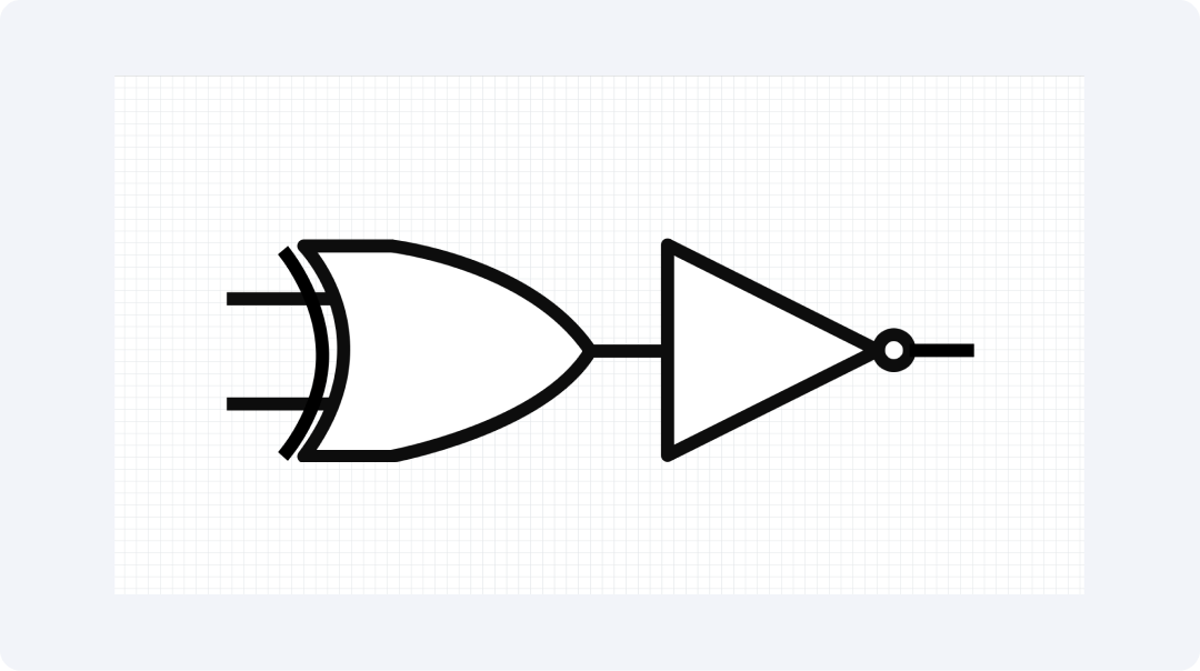
The Inverted XOR gate performs a double-check on different inputs by converting the result through inversion. This makes an XNOR gate. The gate produces high output when all its inputs match each other. The device produces a low signal output whenever the inputs show any difference between them.
The end component of this gate resembles a circle attached to an XOR design. The gate functions to verify the precise correspondence between two values. The gate functions as a component in math checkers and error finders. The device implements this gate to determine whether two inputs match or not.
Flip-Flop
The Flip-Flop contains NOT gates which enable it to store digital information. The device stores a single value between 0 and 1 but it modifies its value only through explicit instructions. The storage capability of digital systems exists between different tasks because of flip-flops.
The device appears as a labeled box which serves as its interface. Digital tools store their short-term memory within flip-flops. The counting process sequences get stored within the Flip-Flop along with data storage capabilities and system state management functions. The functioning of digital tools depends on flip-flops which act as memory storage units.
Explore More NOT Gate Symbols on EdrawMax
EdrawMax provides users with a wide range of NOT gate symbols which they can access from its libraries. The drawing tool provides you access to more than 26,000 electronic symbols. Users can obtain every necessary component for plan development through EdrawMax. The application provides benefits to students as well as makers and professional workers.
What Is EdrawMax?
The interface of EdrawMax presents itself in an uncluttered manner that users can easily operate. The software allows users to produce various plans with minimal time expenditure on research. The drawing software extends its capabilities above basic functionalities to support multiple drawing needs. The software serves beginners and professional users in preparing quick and understandable tech plans.
Let's look at some top things that make EdrawMax great for circuit plans:
- Has over 26,000 marks for all kinds of tech plans
- Lets you drag and drop parts to make plans fast
- Comes with ready plans to help you start quick
- Works on all main computer types
- Saves your work in many file types like PNG and PDF
How to Find More Symbols on EdrawMax?
Step 1Open EdrawMax and Login
Open the EdrawMax app. Sign in with your username and password or use a fast link from social media.
Step 2Start a New Diagram

Click "New" on the main page. Pick "Circuit Diagram" to make a clean sheet to work on.
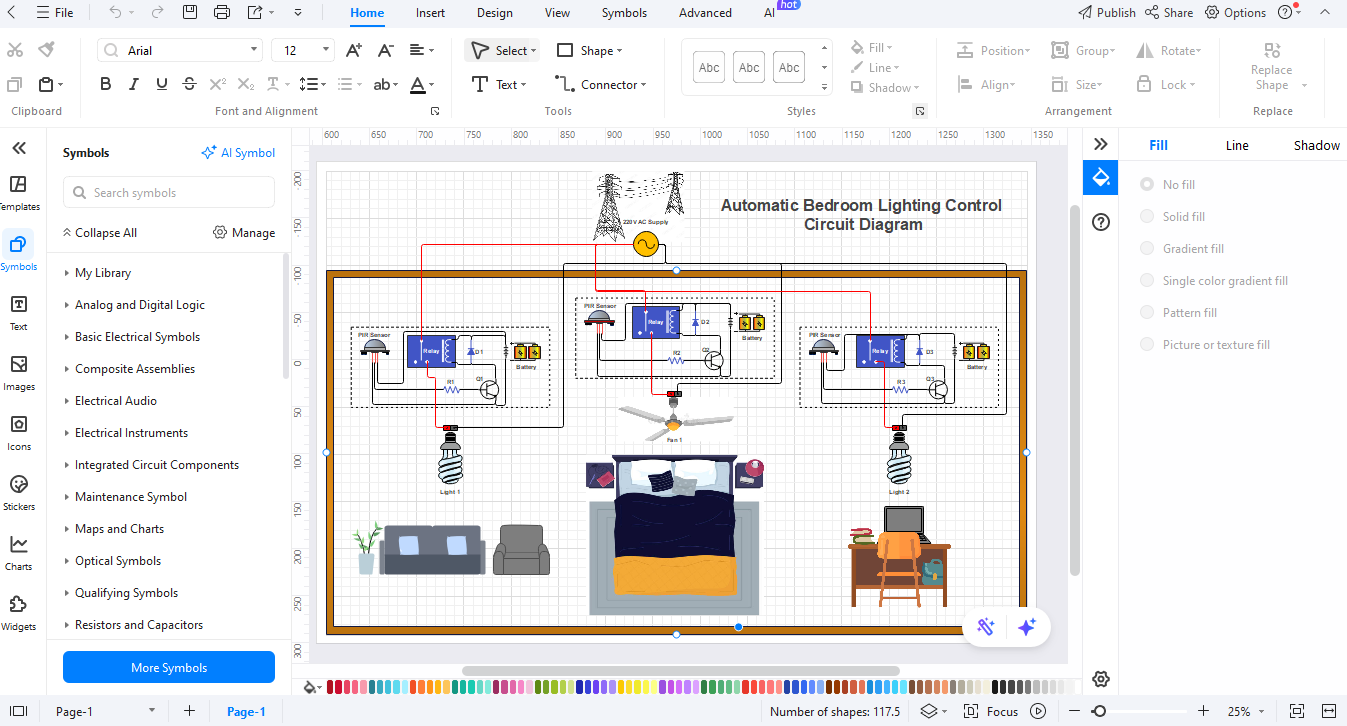
Step 3Access the Symbol Library
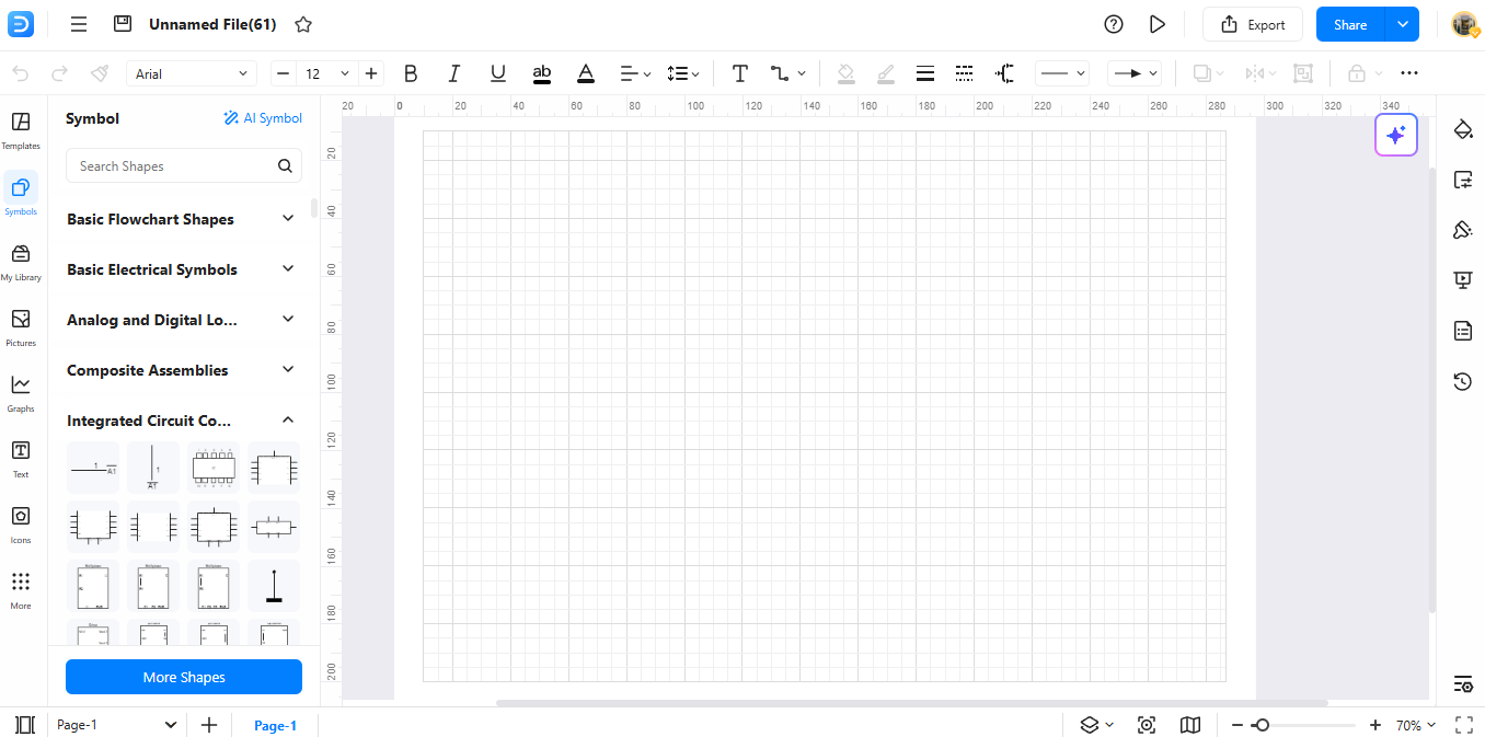
Look for "Symbols" on the left side. Click it to see all the groups. Look in "Electronic Components" for rectifier parts.
Step 4Search for Specific Symbols
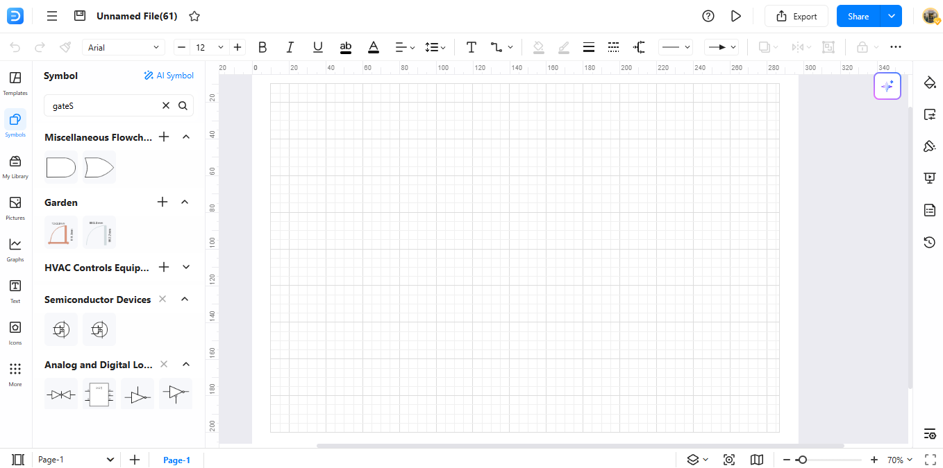
Use the search box at the top of the Symbols menu. Type "NOT gate" to find just what you need for your design.
Step 5Download Additional Symbols
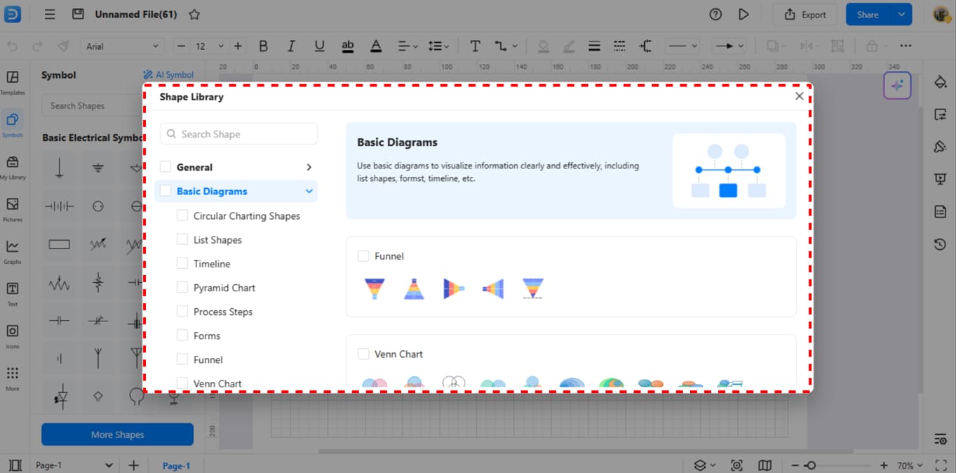
Check the bottom of the library for more choices. Click download to get extra symbol sets if you need them. This saves it to your library for next time.
Step 6Make Your Custom Symbols
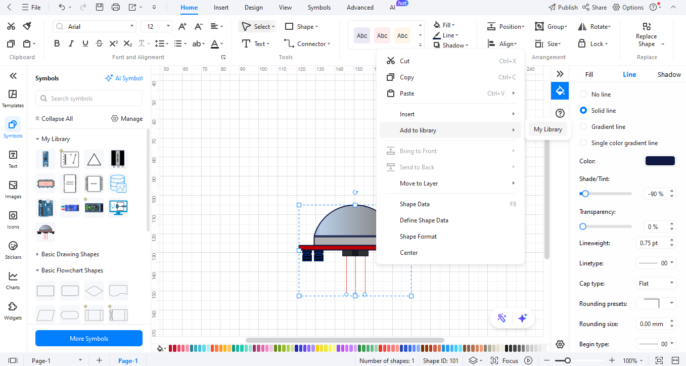
Make your own NOT gate types by using symbols you already have. Right-click on what you made and pick "Add to Library" to keep it for later use.
How to Make a Circuit Diagram on EdrawMax
Step 01Open EdrawMax

Start EdrawMax on your PC or go to EdrawMax Web in your web browser.
All templates below are free to access, view, and edit. You can download the template or the upgraded version for free as well.
Step 2Create a New Project
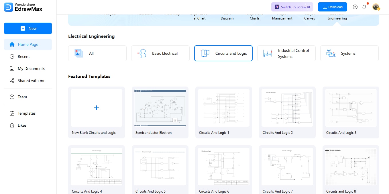
Click "New" and choose "Circuit Diagram" from the list to start.
Step 03Add Circuit Symbols
Look through the symbol list for logic gates and other parts. Drag them onto your page where you want them.
Step 04Customize Your Diagram
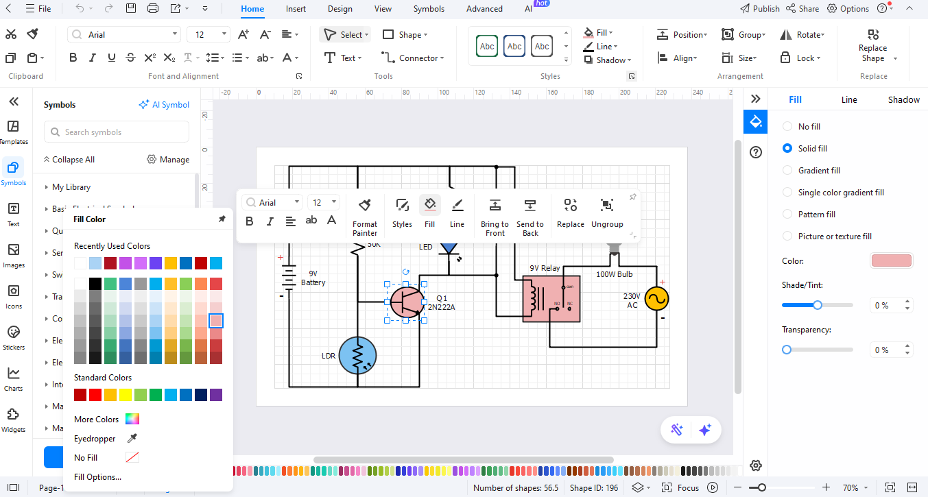
Use the line tools to link parts. Add names and notes to make things clear. Change colors to make it easy to read.
Step 05Export the Diagram
When done, click "Export" to save your work as PNG for the web, PDF for docs, or SVG for sizing.
Ending Notes
The symbols of NOT gates enable circuit creators of all experience levels to work efficiently. The symbols enable difficult concepts to become visible and usable. The software enables users of all experience levels to create professional diagrams through streamlined operations. All users can access its basic tools alongside numerous symbols within the software.
EdrawMax offers users a comfortable environment to create circuits with reliability. The creation of clear NOT gate plans becomes possible because these designs both function properly and present a professional appearance. Test this system right now to experience the straightforward conversion of your concepts into organized circuit diagrams.
AI Diagram Generator
Enter your prompt. Upload files if needed. Generate diagrams, charts, or slides instantly.


