


Rectifiers function to convert alternating current power into direct current power. Most of our everyday tools and toys operate because of their functionality. The operation of both phones and computers depends on rectifiers to function properly.
The guide demonstrates the fundamental rectifier symbols that exist in circuit diagrams. We'll see what each one does. Drawing these parts becomes possible through EdrawMax software. Users who lack deep technical skills can produce excellent diagrams using this tool without difficulty.
In this article
All Common Types of Rectifier Circuit Symbols
Simple Rectifier
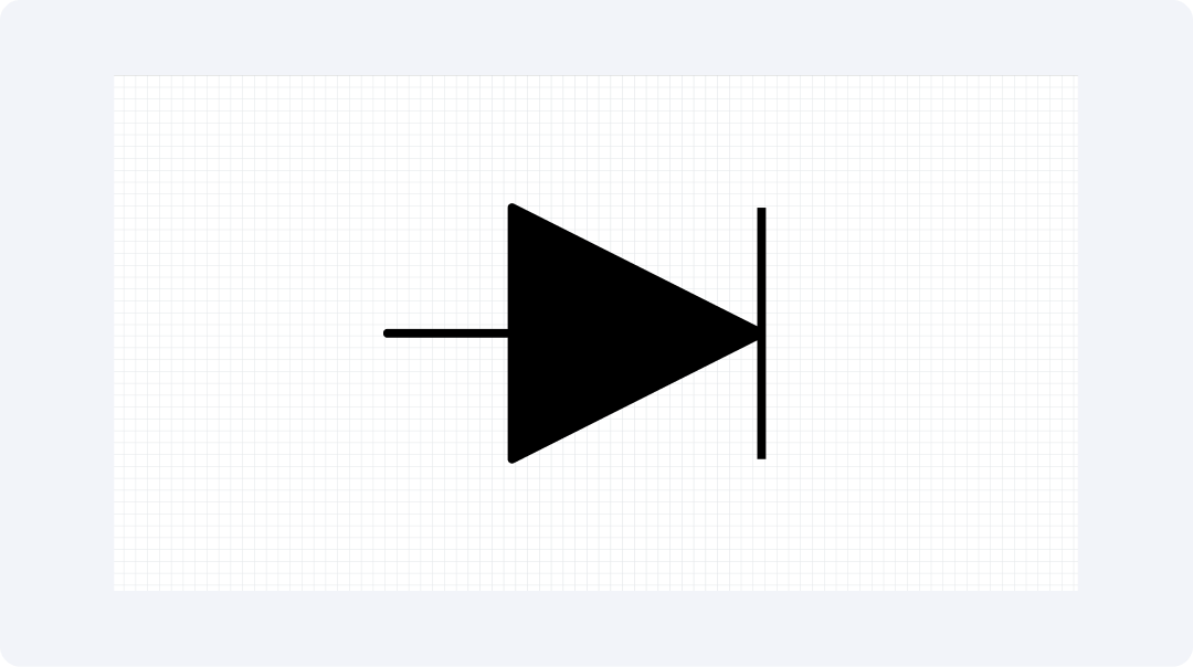
The Simple Rectifier operates as a one-directional power flow device. The device blocks power flow in both directions except through one path. The device transforms alternating current power into direct current pulses for tool usage.
The Simple Rectifier operates as a key component in numerous home appliances. The operation of phone chargers alongside LED lights depends on simple rectifiers. Their basic design leads to lower production expenses. Many basic power units incorporate them because of their usefulness.
Controlled Rectifier
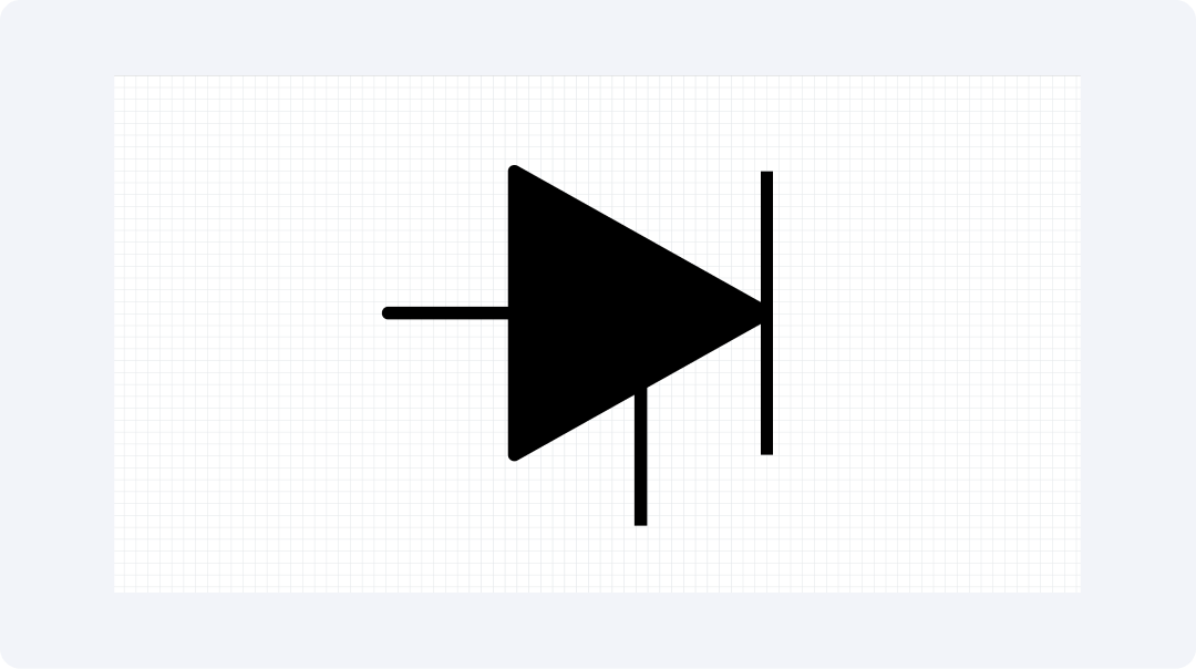
The Controlled Rectifier includes a gate system that controls the duration of power flow. The gate operates as an on-off mechanism to control power transmission. The correct power level can be established through this process.
These electrical components allow lights and fans to determine their operation speeds and brightness levels. Shop tools implement them to operate at specific speeds. These components enable numerous tools at home and work to function properly.
Bridge Rectifier
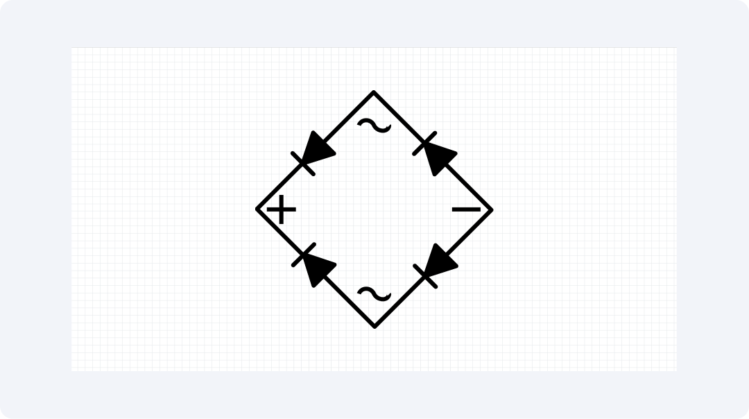
The Bridge Rectifier consists of four square-positioned elements. The square design transforms entire AC waveforms into smooth DC output. The power waste is lower than alternative power conversion methods.
The majority of household tools include these components inside their power supply units. The uniform distribution maintains continuous operation even without interruptions or sudden speed changes. The smooth power supply from the bridge rectifier enables TVs and audio equipment to operate correctly.
Half-Wave Rectifier

During operation the Half-Wave Rectifier selects only the middle portion of alternating current waves. It blocks the other half. The output DC pulses occur at the same frequency as the applied input signals. The design keeps its operation straightforward yet delivers a resulting output that jumps.
The sound waves reach radios through these components. These charging devices also incorporate this feature. Power flow instruction is provided to new students by these devices. These components serve as introductory learning tools because of their basic operational design.
Full-Wave Rectifier

The Full-Wave Rectifier uses all parts of the AC wave. This makes twice as many DC pulses as half-wave types. The flow is more smooth with less need to clean it up.
Good power units need these for steady flow. They stop buzzing in sound gear. Health tools also use them when safe flow is key. They waste less power than simple ones.
Turn-Off Rectifier
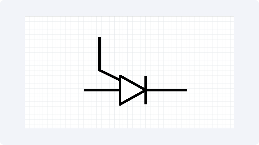
The Turn-Off Rectifier determines both power-on and power-off operations. The Turn-Off Rectifier functions to deliver quick flow termination capabilities. The input signals determine the exact times for operation activation and deactivation.
Backup power units implement these devices to perform rapid power switching during main power outages. Big tools implement these devices to achieve safe stopping functions. The device operates effectively to control powerful electricity flows correctly.
Rectifier Inverter
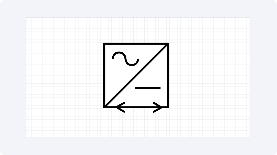
The Rectifier Inverter completes both AC to DC conversion and DC to AC transformation in a single device. First, it turns AC into DC. The device converts DC to AC power output at a different speed rate.
These devices enable sun power units to connect to home wiring. Car power outlets require these components for operation. Such devices enable different power types from various sources to combine in one residential power grid.
Precision Rectifier
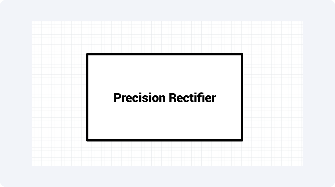
A precision rectifier circuit consists of operational amplifiers and diodes. Basic rectifiers differ from precision rectifiers because they deliver accurate signal rectification for small signals without creating any distortion.
The specialized circuits provide better performance than standard diodes by addressing their forward voltage drop limitation. Precision rectifiers maintain low-voltage signals which would be eliminated by standard rectifier circuits. These circuits keep high accuracy for audio signals.
Explore More Rectifier Symbols on EdrawMax
The plan making process benefits from various rectifier symbols available in EdrawMax. The software tool provides access to over 26,000 symbols for users to choose from. Users of EdrawMax will find everything required to create professional plans through their study activities or their work responsibilities or their interest in building things.
What Is EdrawMax?
EdrawMax enables users to create professional plans without great effort. The application lets users create simple visuals that show how components connect. The program enables quick learning so you can create neat plans.
The following features of EdrawMax make it an excellent tool for creating plans:
- Has more than 26,000 symbols for all kinds of plans
- Uses drag-and-drop to make drawing fast
- Gives you ready-made starts to work from
- Works on all main types of computers
- Saves work as PNG, PDF, or other file types
- Keeps your files safe in the cloud
How to Find More Symbols on EdrawMax?
Finding the right symbols in EdrawMax is easy:
Step 1Open EdrawMax and Login
All templates below are free to access, view, and edit. You can download the template or the upgraded version for free as well.
Open the EdrawMax app. Sign in with your username and password or use a fast link from social media.
Step 2Start a New Diagram

Click "New" on the main page. Pick "Circuit Diagram" to make a clean sheet to work on.
Step 3Access the Symbol Library
Look for "Symbols" on the left side. Click it to see all the groups. Look in "Electronic Components" for rectifier parts.
Step 4Search for Specific Symbols
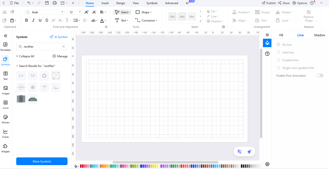
Use the search box at the top. Type "rectifier" to find just what you need fast.
Step 5Download Additional Symbols
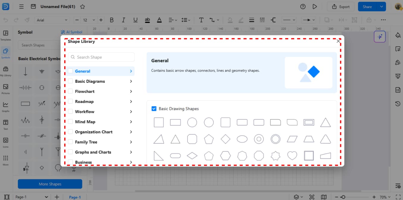
If you need more symbols, click "More Symbols" at the bottom. Pick and add more groups of parts to your tool box.
Step 6Make Your Custom Symbols
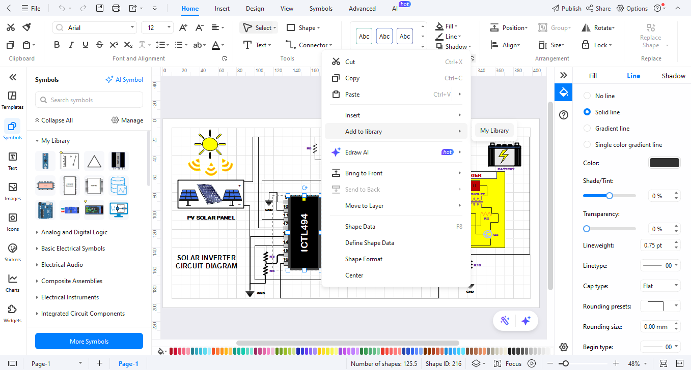
Make your own parts by joining shapes. When done, right-click and pick "Add to Library" to save for next time.
How to Make a Circuit Diagram on EdrawMax
Making a rectifier plan is easy with EdrawMax. Just do these steps:
Step 01Open EdrawMax

Start EdrawMax on your computer or go to EdrawMax Web to use it on the web.
Step 2Create a New Project
Click "New" and pick "Circuit Diagram." This gives you a blank page with a grid to help line things up.
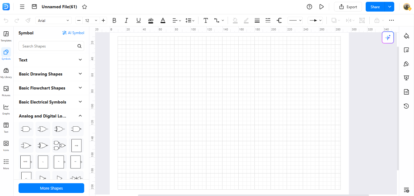
Step 03Add Circuit Symbols
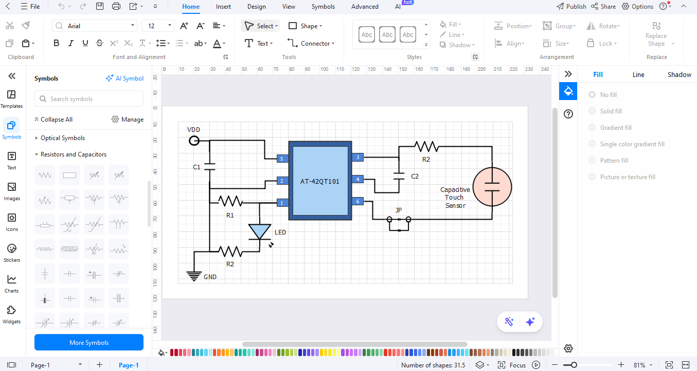
Find rectifier parts in the side list. Drag them onto your page. Add more parts like power points, gates, and wires too.
Step 04Customize Your Diagram
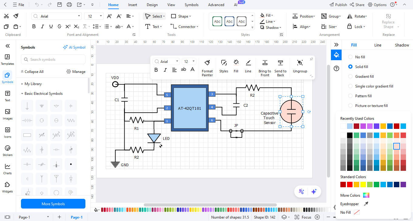
Join your parts with lines to show wires. Add names to tell parts apart. Use the text tool to add notes that say how it all works.
Step 05Export the Diagram
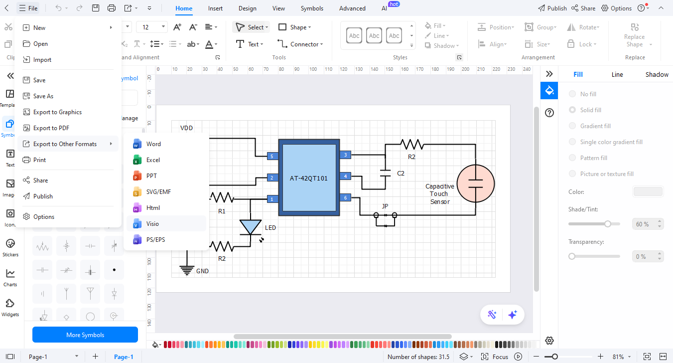
When you finish, click "Export" to save your work. Pick JPG/PNG for an image file, PDF for print, or other types as you need.
Ending Notes
The use of rectifier symbols leads to clearer plans that are easier to understand. Simple visual representations emerge from complex technology concepts through their work. All required elements for drawing plans exist within the EdrawMax platform.
Experience the effortless design capabilities of EdrawMax by starting your trial today. The tool functions equally well for skilled and unskilled users of this work. Your ideas will materialize as you create your rectifier plans.
AI Diagram Generator
Enter your prompt. Upload files if needed. Generate diagrams, charts, or slides instantly.


