- Templates
- Circuit diagram templates
- Digital alarm clock circuit diagram
About this digital alarm clock circuit diagram
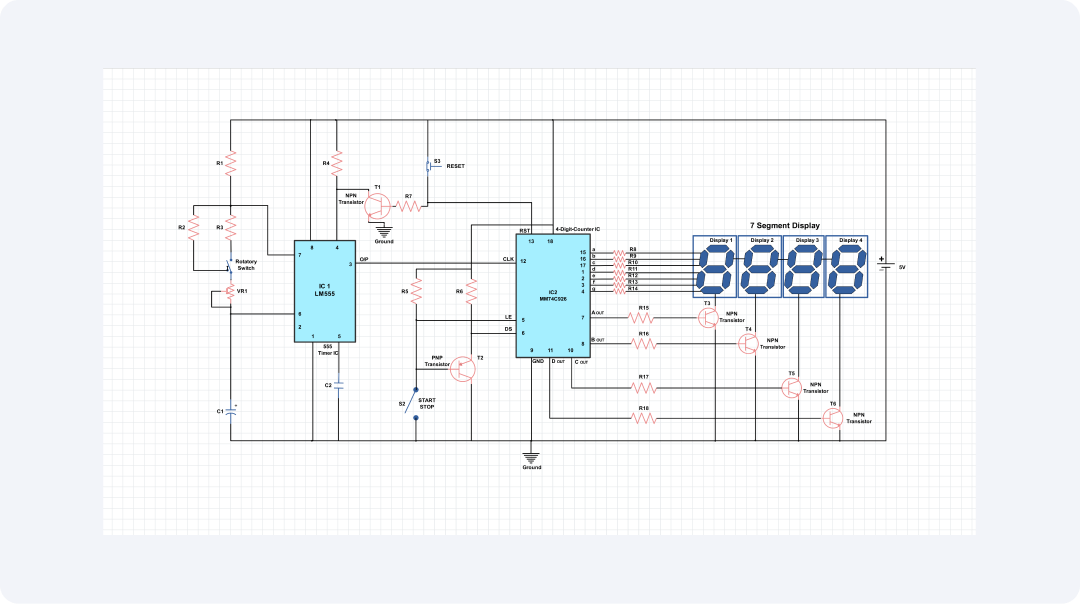
The circuit diagram is for a simple digital alarm clock. It uses a 7-segment display to show the time. A 555 timer IC produces the alarm tone. A manual switch push button is incorporated in the circuit as an alarm setting and buzzer as alarm signaling.
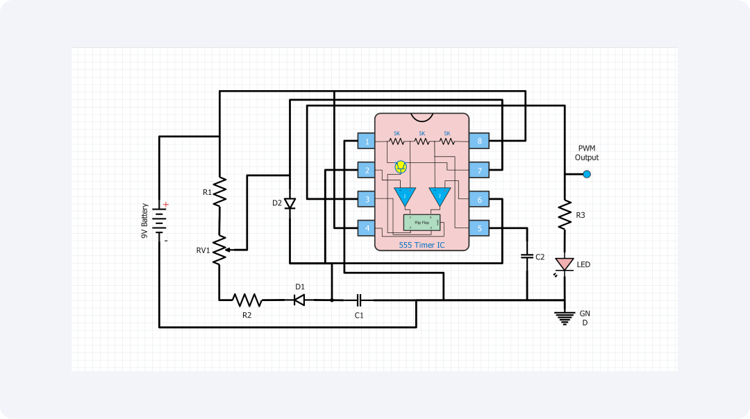
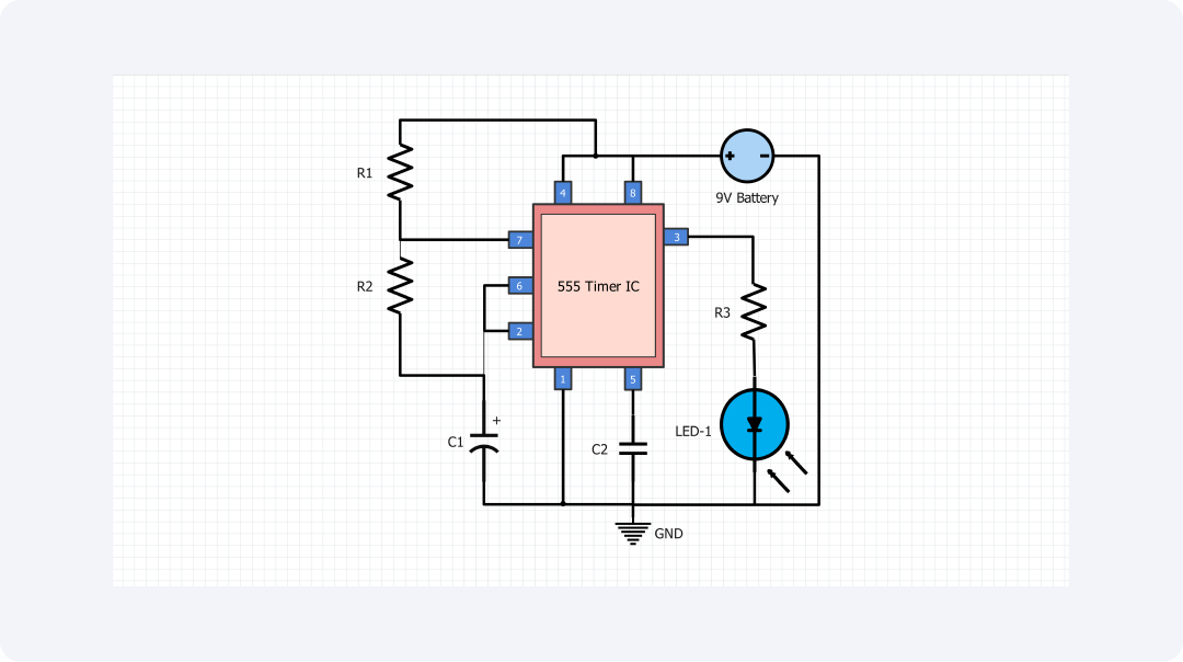
The 555 timer is an effective chip that can create a wide number of waveforms such as square waves, triangle waves, and saw waveforms. In this circuit, the 555 timer is set to be an astable oscillator that will produce a square wave used to drive the 7-segment display.
The 7-segment display has seven elements, which are formed by seven LEDs that allow numeric values from zero to nine. 555 timer output signal is used to drive a decoder/driver IC, which drives each segment of the display to show time on the 7-segment display.
The push-button switch is used to set the time at which the alarm will be required. On pressing the button, the user has the ability to control the time on the 7-segment display for the setting of the alarm time. After setting the alarm time, the 555-timer shown below will produce a signal as an alarm at the expected time.
This alarm signal is used to switch on a buzzer whereby the alarm will be sounded. The alarm can in turn be silenced by the push-button switch once pressed by the user.
Digital alarm clock circuits are very useful. It has the following uses. For personal use, it may be used as a home alarm clock or an item to time cooking. In an educational setting, it assists in explaining to the students on digital electronics and circuit designing.
Moreover, it can be installed into industrial products, providing value in business applications. In general, it is useful for both individuals and schools to use it.
It may be of use to anybody interested in constructing a basic digital alarm clock or that has an interest in learning more about digital alarm clocks.
Related templates
Get started with EdrawMax today
Create 210 types of diagrams online for free.
Draw a diagram free Draw a diagram free Draw a diagram free Draw a diagram free Draw a diagram free