- Templates
- Circuit diagram templates
- Thermostat circuit diagram
About this thermostat circuit diagram
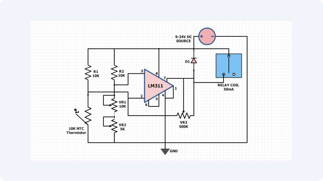
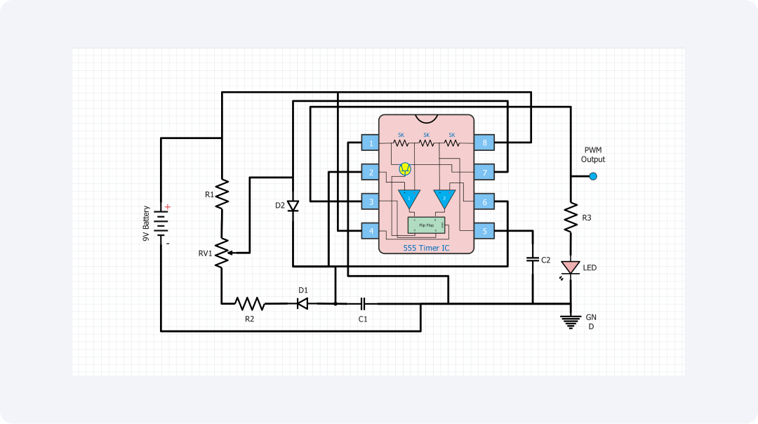
Pulse width modulation, or PWM, is a common technique in power sources. It controls the power level in various electronic devices. In the present circuit diagram, the essential elements and operation of a PWM control system have been depicted.
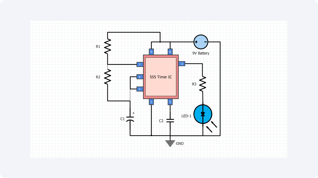
The entire circuit is based on the 555 timer IC which is used in an astable multivibrator configuration. The 555 timer produces a square wave. It oscillates continuously. The output pulse width depends on the resistor-capacitor network connected to the 555.
The potentiometer RV1 sets the circuit's impedance. So, controlling the PWM signal's duty cycle controls the average power to the load. The PWM output signal is then connected to an LED for the purpose of displaying the duty cycle of the carrier signal.
The circuit shows the idea behind pulse width modulation. The pulses, in this case, have a width that changes. It is proportional to the amplitude of an input analog voltage. This makes the PWM circuits very appropriate for applications such as the fading of LEDs, control of speed of motors, and power control.
This PWM circuit is very flexible. Its frequency and variable duty cycle can be tuned. So, it is widely used in various electronics and control systems.
The use of simple, easy-to-find parts makes this PWM circuit design simple and easy to integrate. It uses a common 555 timer IC, resistors, and capacitors.
Aside from the simplest of applications wherein it only uses LEDs to light up, this PWM circuit can be further developed and improved for usage. It could be applied in the speed control of a DC motor through the modulation of the pulse width signal.
This would enable the desired speed and speed range to be achieved within a given accuracy suitable for applications such as Robotics, automation, and industrial equipment.
Another field is power electronics. PWM techniques widely control and manage power conversion. The PWM circuit could be incorporated into a switching power supply circuit and into an inverter circuit to act to control the output voltage or current while conserving energy in uses such as solar charge controllers, charge controllers UPS and variable speed drives.
In lighting control, this PWM circuit could regulate the brightness of LED lights or create lighting effects. We can now smoothly tune LED brightness. We do this by varying the duty cycle of a PWM signal. This provides an efficient, adjustable solution for homes, industries, and design work.
The basic PWM circuit's versatility is clear in the examples. They show just a fraction of its many uses in various systems and projects. The low cost, flexibility, and easy availability of the 555 timer IC make this circuit appealing to all. It attracts beginners, amateurs, and professional engineers.
Related templates
Get started with EdrawMax today
Create 210 types of diagrams online for free.
Draw a diagram free Draw a diagram free Draw a diagram free Draw a diagram free Draw a diagram free