- Templates
- Circuit diagram templates
- Pulse width modulation circuit diagram
About this pulse width modulation circuit diagram
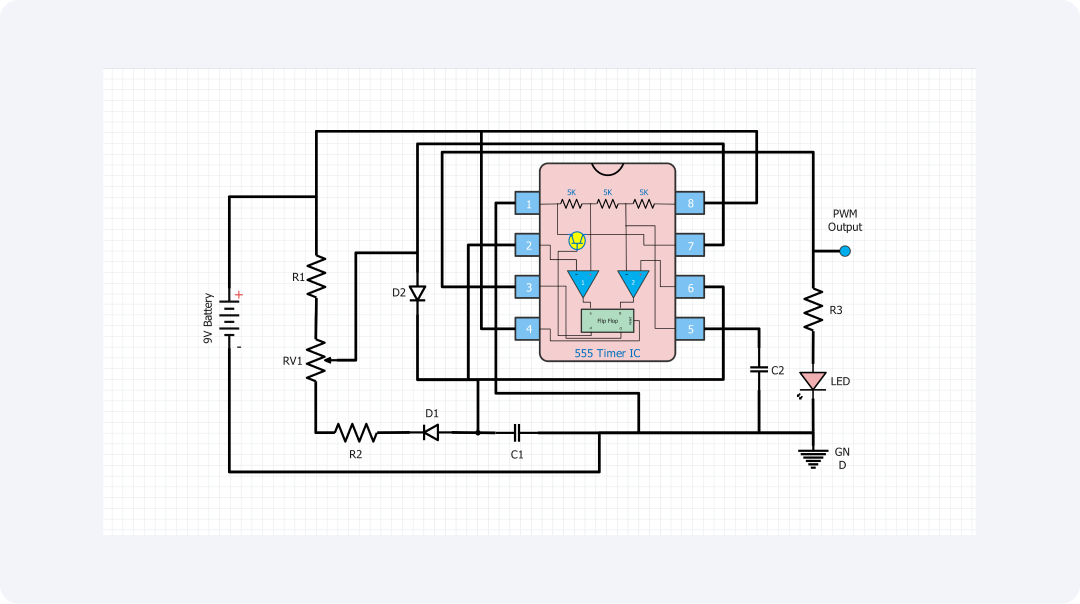
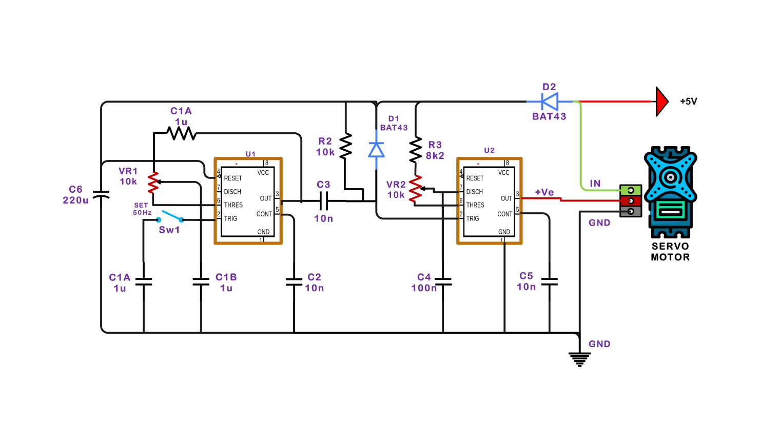
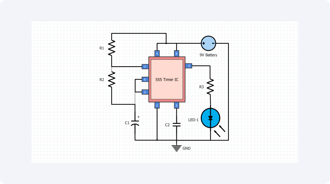
Pulse width modulation (PWM) is a general technique applied for controlling the powers in numerous electrical applications. This circuit diagram aims to depict those parts most basic to a PWM control mechanism and its operation.
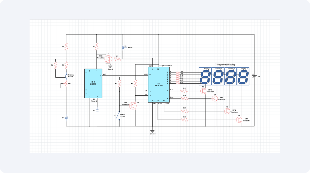
The main focus of this circuit lies on the 555 timer IC and is realized in an astable multivibrator configuration. The 555 timer produces a triangle waveform by sending equal-amplitude pulses.
The pulse width is controlled by the resistor and capacitor values. By adjusting the potentiometer RV1, you can change the PWM signal's duty cycle. This controls the average power delivered to the load.
The PWM output signal is then utilized to drive an LED to indicate the duty cycle value clearly in order to observe the variation effectively. This simple circuit shows how pulse width modulation works.
The pulse width control signals match the amplitude of the input analog signal. PWM circuits have adjustable duty cycles. So, they can be used for LED dimming, motor speed control, and power control.
This PWM circuit is flexible. You can easily adjust the frequency and duty cycle to meet the needs of a specific project or control system.
In addition to those, the PWM circuit design based on readily available components like the 555 timer IC as well as resistors and capacitors makes it all the much easier and operational to implement.
Related templates
Get started with EdrawMax today
Create 210 types of diagrams online for free.
Draw a diagram free Draw a diagram free Draw a diagram free Draw a diagram free Draw a diagram free