- Templates
- Circuit diagram templates
- IC FM radio circuit diagram
About this IC FM radio circuit diagram
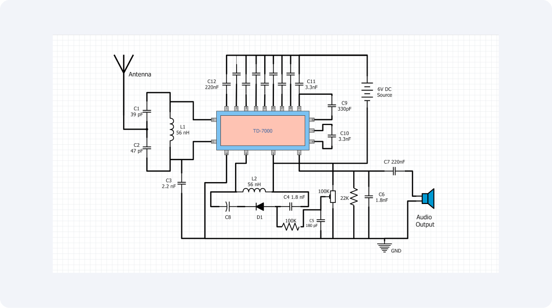
The diagram shows the circuit that is designed to be a small FM radio receiver that uses the TD-7000 IC. The diagram displays possible connections and main elements for a simple FM radio outlining the features necessary to produce and amplify an FM signal.
The key part of the IC FM radio circuit is the TD-7000. It is a signal processing IC, designed for FM radio use. The basic circuit is initiated by an antenna to capture the FM radio waves that are followed by capacitors and an inductor creating a tuning circuit.
The QWT is useful for preliminary filter selection and tuning of load impedance. When the TD-7000 receives the signal, it amplifies it. Then, a mixer generates an intermediate frequency. From this, it demodulates audio data from the FM carrier.
On the output side, the TD-7000 has an audio processing unit that uses capacitors and resistors to filter and equalize the audio frequency. Traditionally, the circuit is operated from a 6V DC source and RC bypass capacitor for cleaning the supply.
Also, an inductor and a diode are in the output path. They allow for an automatic gain control circuit to sustain the output level.
This FM radio circuit shows how modern integrated circuits can be efficient and relatively small in size. For FM reception, the design uses only the TD-7000 IC and does not require the use of many additional discrete components. This method not only saves manufacturing costs but also enhances product uniformity in its performance.
Due to its circuit design, this unit may be used in portable radios, car stereos, or simply incorporated into a more elaborate audio system. It also bears a reasonable number of components and a relatively simple structure which makes it a good teaching aid for students studying RF circuits and signals.
In conclusion, this is a simple and compact IC FM radio circuit diagram that reveals all the basic workings of FM radio reception. It describes a single chip with various radio features. It aims to improve performance by using the right passive components. This circuit shows how to use modern design techniques in electronics.
Related templates
Get started with EdrawMax today
Create 210 types of diagrams online for free.
Draw a diagram free Draw a diagram free Draw a diagram free Draw a diagram free Draw a diagram free