- Templates
- Circuit diagram templates
- Capacitive touch sensor circuit diagram
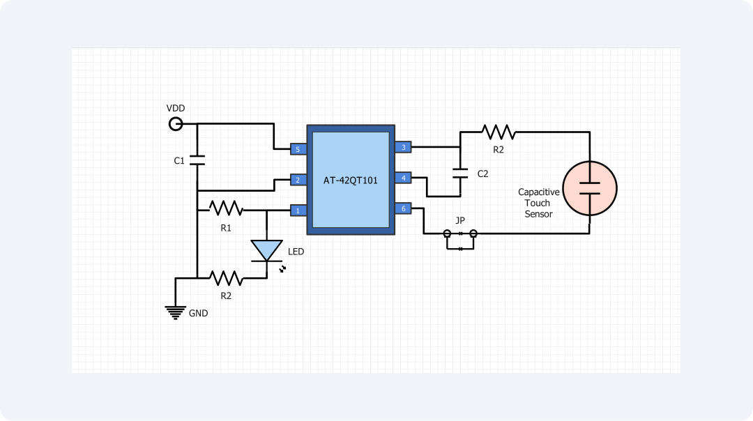
About this capacitive touch sensor circuit diagram
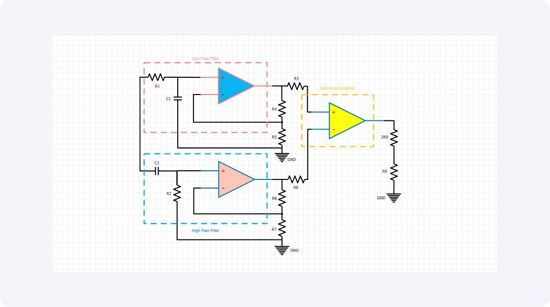
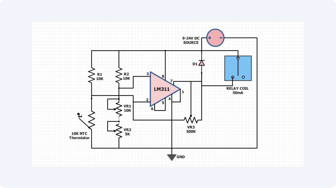
A capacitive touch circuit is one of the simplest and most efficient circuits that can operate the detection of a human or any metallic object. The above circuit is a simple capacitive touch control circuit. It uses an operational amplifier, or op-amp, as the comparator.
The circuit connecting the several components comprises an operational amplifier (op-amp), two resistances (R1&R2), and one capacitance (C). The capacitor is with the op-amp to the non-inverting terminal. The other op-amp terminal is connected to the battery's negative terminal.
Capacitance increases when a conductive object is near the capacitor. It decreases with an insulating material between the conductors. This change in capacitance results in a change in the voltage at the non-inverting input of the op-amp.
If the non-inverting input of the op-amp is higher than the inverting input, it will output a high voltage. This can be followed by the use to generate high voltage to power an LED, a buzzer on other output products.
The capacitive touch circuit has many possible uses. They can be operated to locally manage conditions such as lights, doors, and any other device. The blanking time may also be applied to design a proximity sensor or for sensing the presence of water.
The capacitive touch sensor circuit has many uses. It can work on portable devices like smartphones and tablets. It can also work in fixed industrial and commercial applications, like security systems and electronic screens. Its ability to sense conductive materials lets it be used in many gadgets. This enhances a better, more responsive touch experience.
This diagram provides a clear image of the touch sensor. For anyone interested in, or wanting to, make capacitive touch circuits, this is a very useful asset. And the diagram components are easy to find.
Related templates
Get started with EdrawMax today
Create 210 types of diagrams online for free.
Draw a diagram free Draw a diagram free Draw a diagram free Draw a diagram free Draw a diagram free