- Templates
- Circuit diagram templates
- IR remote control circuit diagram
About this IR remote control circuit diagram
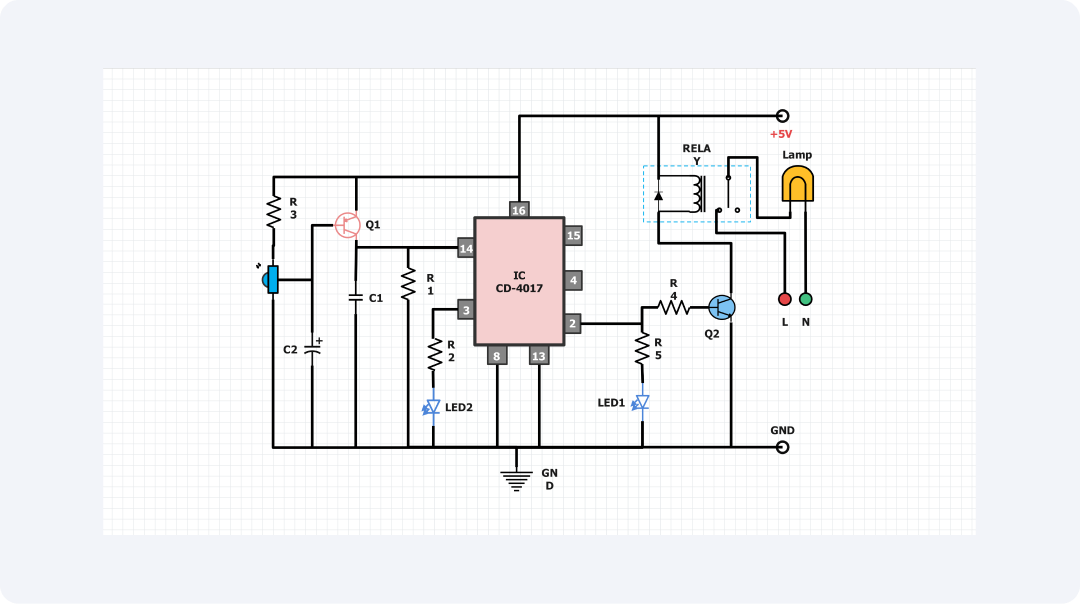
From this circuit diagram, the general design of a simple IR remote control system based on the CD-4017 integrated circuit can be seen. CD-4017 is a CMOS decade counter/divider that forms the core of this remote-control circuit and a shaft 4403 variable rotary decimal switch.
The IR remote control circuit includes a photodiode. LED2 is the infrared receiver, a phototransistor. This component receives the modulated infrared signal that is ejected from the remote-control unit. These signals are then taken to the CD-4017 integrated circuit that acts to decode the input pulses to produce output signals.
C2 supplies power decoupling of the IC while R3 and C1 form an input conditioning RC circuit. When the CD-4017 perceives an acceptable IR signal, it switches on a relay that the circuit uses in managing other output equipment such as lamps.
Both the relay as well as the lamp are the output part of this remote-control system. Resistor R1 and transistor Q1 enable the relay to switch on other devices using a remote control.
For user feedback, resistors R4 and LED1 come into the circuit to give a visible indication when the relay is on by lighting up. On the same circuit, an application of resistor R5 and transistor Q2 enables a driver circuit to regulate the functionality of the lamp.
This IR remote control circuit is a basic use of the CD-4017 IC. It could be used in home automation, lighting, and appliance control.
Its few components make it ideal for amateurs, inventors, and techs. They can use it to add remote control to their projects. This flexibility means we can improve the circuit in the future. For example, we can add more output device connections, multi-channel control, or programmable features.
Related templates
Get started with EdrawMax today
Create 210 types of diagrams online for free.
Draw a diagram free Draw a diagram free Draw a diagram free Draw a diagram free Draw a diagram free