- Templates
- Circuit diagram templates
- Heat sensor circuit diagram
About this heat sensor circuit diagram
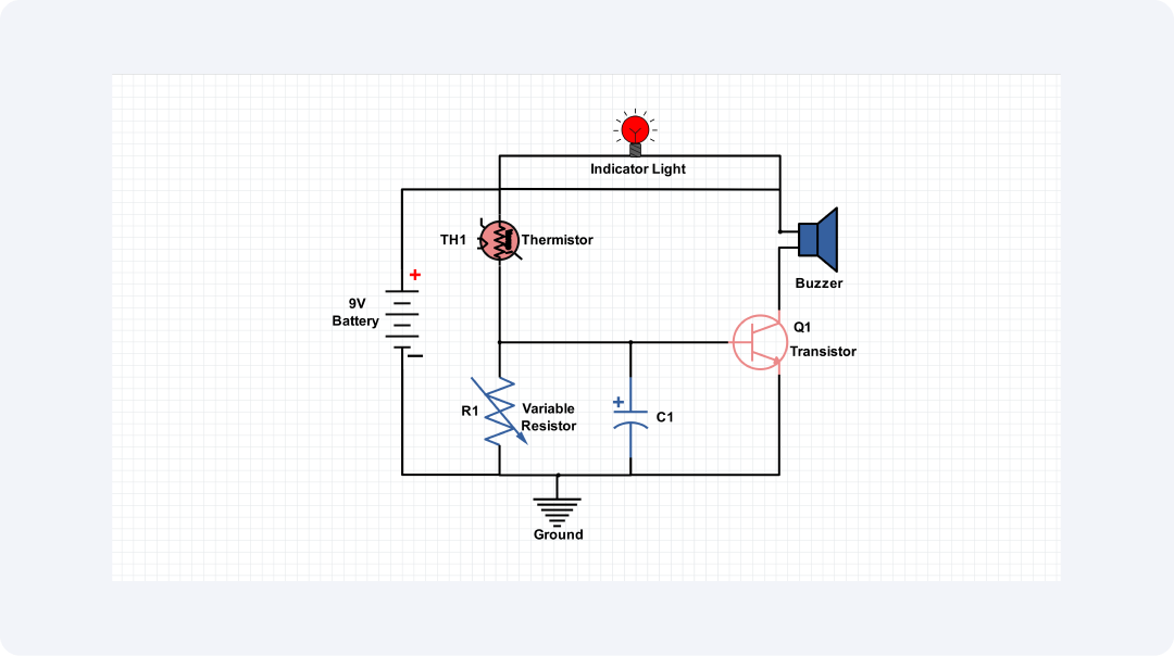
This circuit diagram shows a simple heat sensor circuit that people can use to measure the changes in temperature. It consists of a thermistor, which is a resistor that possesses a characteristic of resistance to temperature.
The thermistor is connected in series with a variable resistor, R1, and a transistor Q1. The thermistor's opposing force reduces as the temperature rises. This is because the resistance decreases as the temperature increases. This decrease in resistance increases the current through the transistor. It turns on the buzzer and lights the indicator.
Another unique feature of the circuit is that there is a variable resistor through which you can balance it. It means that by tuning the resistor R1 you can define the temperature at which the buzzer and indicators are on.
Utilizing the heat sensor circuit, the first real application is temperature measurement. It can measure the temperature of a room, machine, or process. It ensures that ideal conditions are met. This capability is necessary for a comfortable stay and work in different conditions.
The circuit can also be used for temperature alarms. It will sound an alarm if the temperature exceeds a set limit. It is also useful to be connected to a heating or cooling system to control the system's operations according to the prevailing climate. This functionality helps to improve safety and energy, so it will be a useful tool in many cases.
Engineers often want to know everything in a heat sensor before building the circuit. The diagram is clear and uncluttered and all the components are easily accessible in the market if not locally then from online sources.
Related templates
Get started with EdrawMax today
Create 210 types of diagrams online for free.
Draw a diagram free Draw a diagram free Draw a diagram free Draw a diagram free Draw a diagram free