- Templates
- Circuit diagram templates
- Water level indicator circuit diagram
About this water level indicator circuit diagram
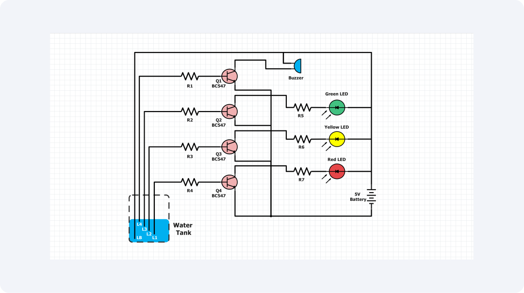
This circuit diagram shows a water level indicator circuit which indicates the level of water in a tank. The elements included in this circuit are transistors, LEDs, and a water tank used in the circuit including level sensing devices.
The water tank is symbolized by the two blue rectangles L1 and L2 which are level sensors in the model. The arrangement is such that, as the water level rises, it contacts the above sensors. This completes the circuits and makes the transistors and LED dials blink.
These transistors are Q1, Q2, Q3, and Q4. They act as switches. When the water touches the sensors, the LEDs light up. The resistors R1 to R4 restrict the current through the LEDs so that they will work fine.
The green, yellow, and red LEDs indicate the water level; the green LED corresponds to the low water level, the yellow to medium water level, and the red to high water level. The buzzer, which is in parallel with the red LED, gives an alarm sound when the water level is at the maximum allowed level.
This water level indicator circuit can be easily utilized in residential water tanks, industrial process control applications, and agriculture water irrigation control systems. The circuit helps users monitor and control fluid levels. A threshold level is easy to find using the visible and audible alerts.
The simple design and use of cheap, easy-to-find parts make the water level indicator circuit here a cheap, practical solution. Also, we can improve the design's flexibility. We can do this by changing the sensors' positions or adding features. These could include remote monitoring or water control to meet the application's needs.
Related templates
Get started with EdrawMax today
Create 210 types of diagrams online for free.
Draw a diagram free Draw a diagram free Draw a diagram free Draw a diagram free Draw a diagram free