Online HVAC drawing software
Try an intuitive HVAC modeling software. Use its vast collection of HVAC templates and symbols to produce detailed thermal ventilation plans.
Why Use EdrawMax HVAC Drawing Maker?
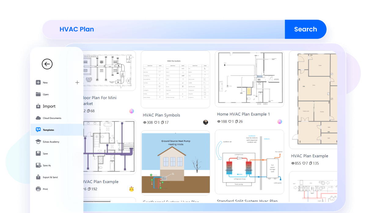
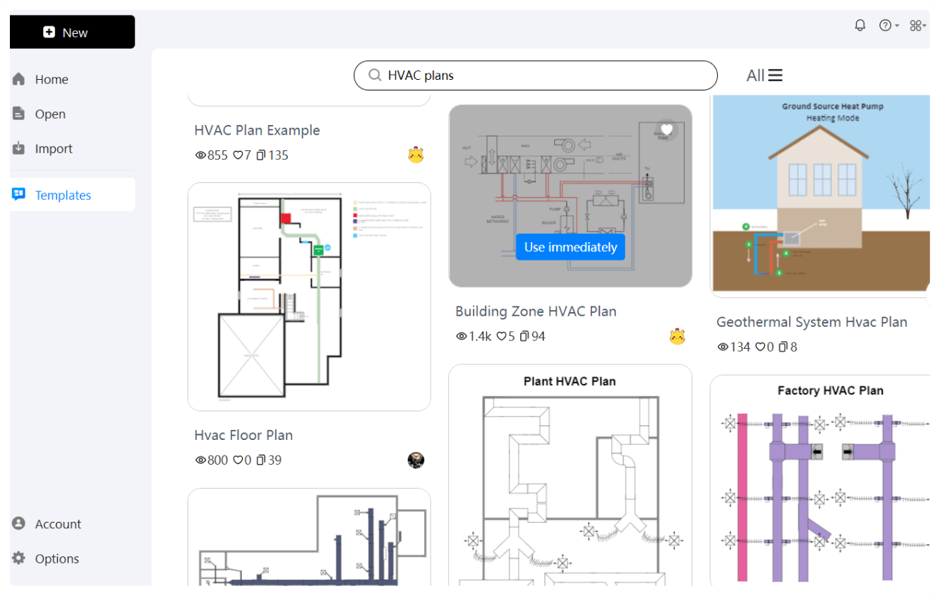
Worrying about your design skills? Worry no more with EdrawMax’s massive template community. It has thousands of HVAC plans, ranging from supermarkets to office space, residential buildings, ductless systems, and more. Plus, the intuitive interface makes editing these samples easier.
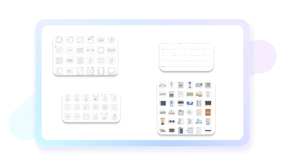
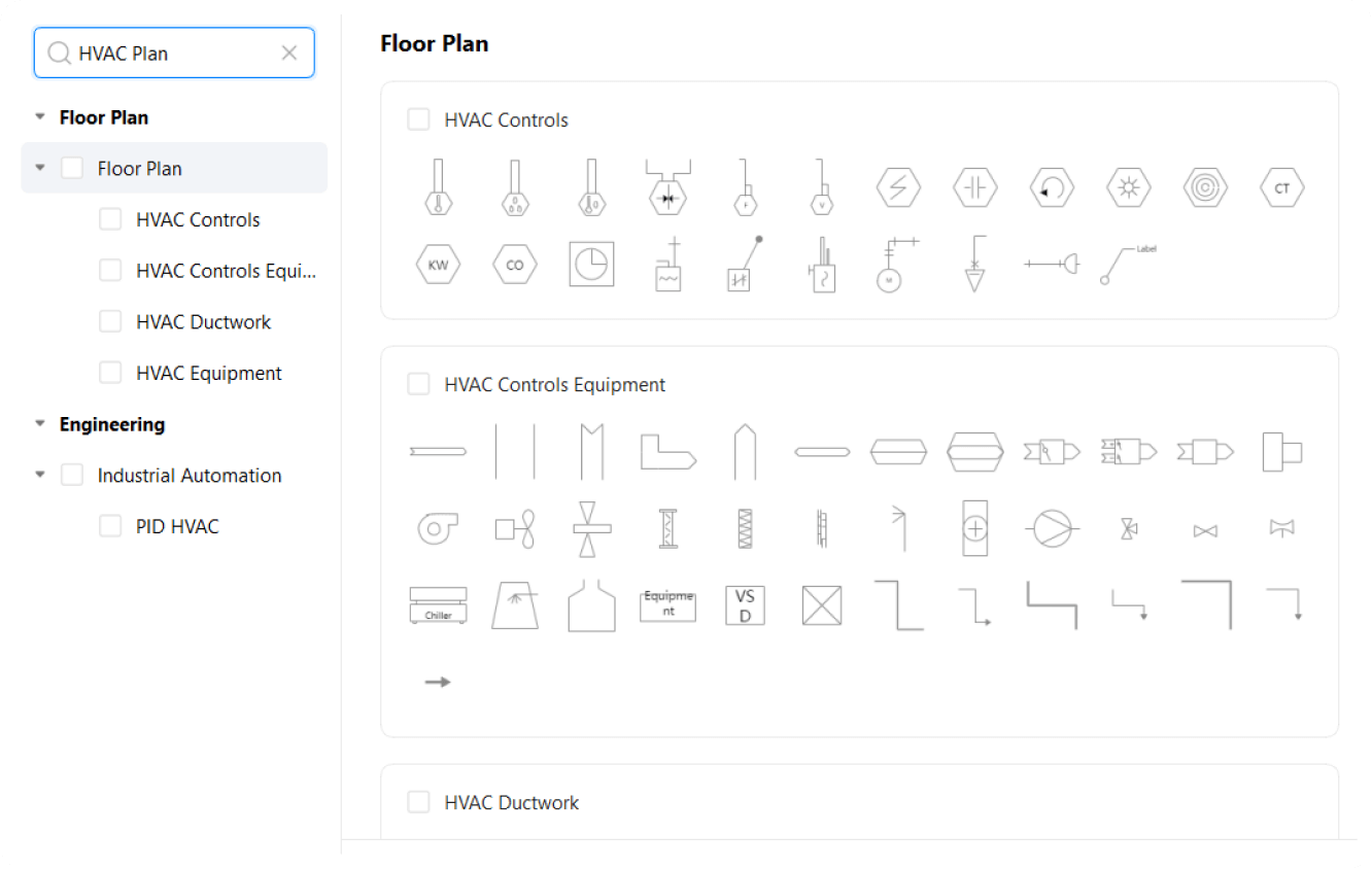
This HVAC drawing software features a massive symbol library with vector icons and shapes. From HVAC ductwork to equipment, ventilation support, and heating elements, you will find all types of symbols important for HVAC diagrams. Just drag and drop them onto the canvas and create intricate plans.
EdrawMax has built-in measurement options to help users with accuracy. With this, you do not have to worry about realistic dimensions, as it allows revising your HVAC plans as per the desired scale. It even lets users change the proportions of individual objects on the canvas.
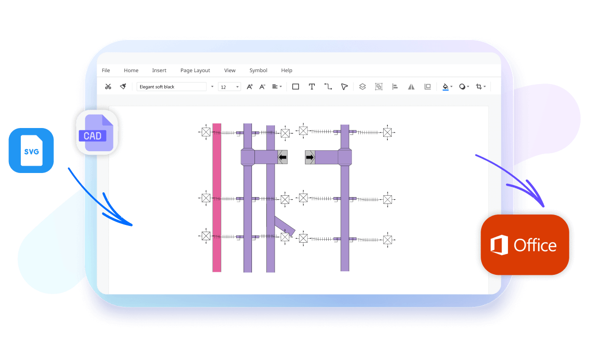
EdrawMax is a solid affordable CAD and Visio substitute, especially for engineering diagrams. It allows importing previous projects from Visio and AutoCAD and further editing them with EdrawMax’s resourceful toolkit. Once done, you can also export them in a Visio format.
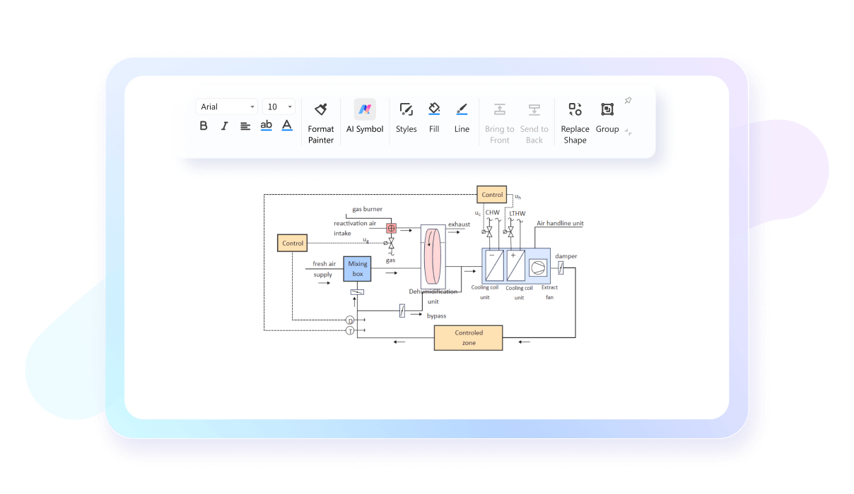
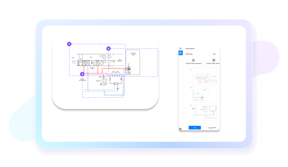
EdrawMax is a useful corporate tool with a built-in presentation mode. Here, you can create, emphasize, and display every significant detail of your ventilation and thermal diagrams. You are also free to present your work in full screen or export it in a PPT format.
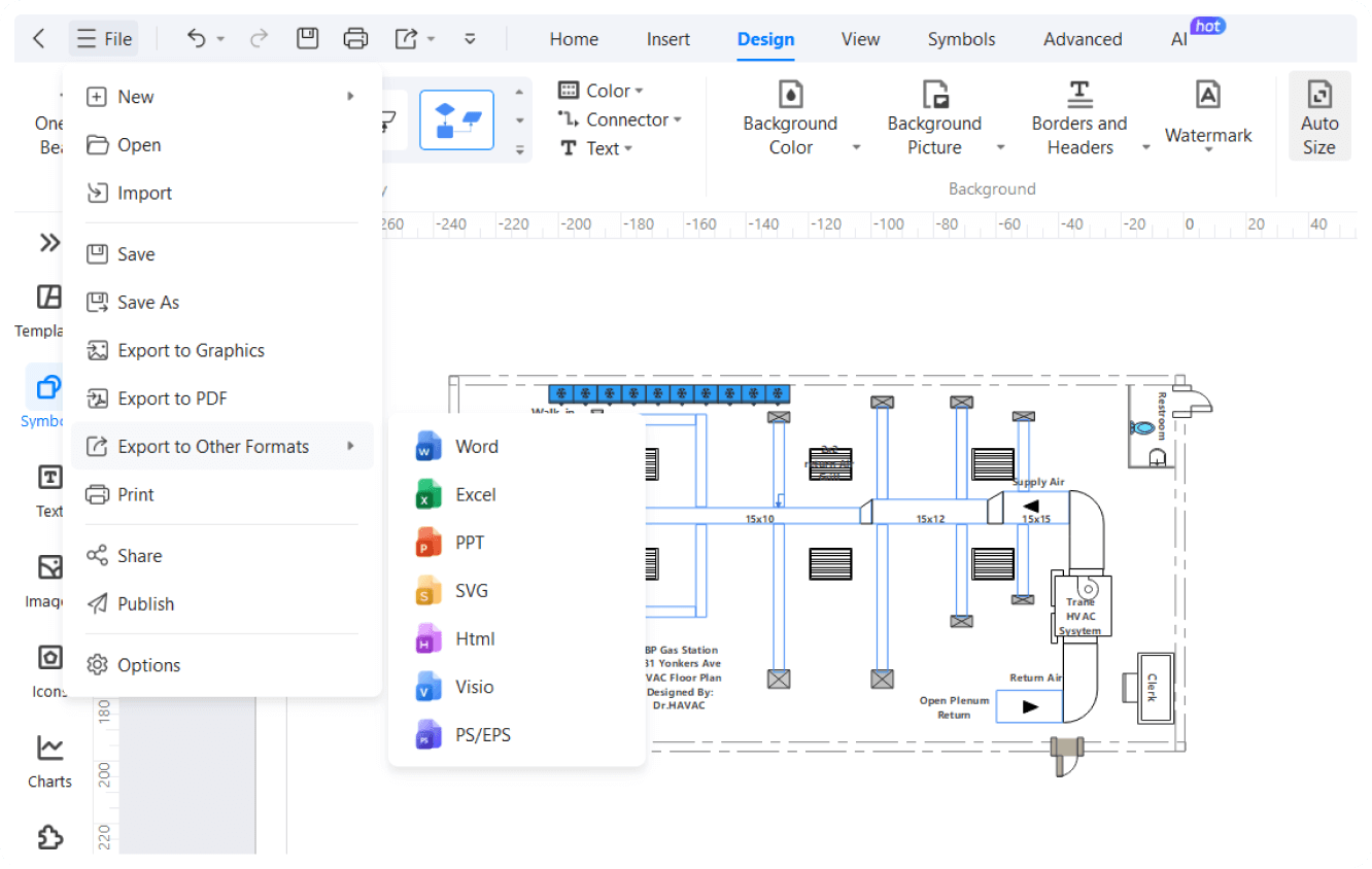
Share your heating and ventilation diagrams however you like. EdrawMax allows you to export their work in over 10 formats, including Visio, PNG, JPG, PDF, and more. Alternatively, you can embed your diagrams in emails, post them on social media, or print them directly.

How to make HVAC diagrams using EdrawMax?
What our users say
More HVAC Tools
Discover more AI-powered diagram makers to boost your productivity.
FAQs About EdrawMax HVAC Tools
-
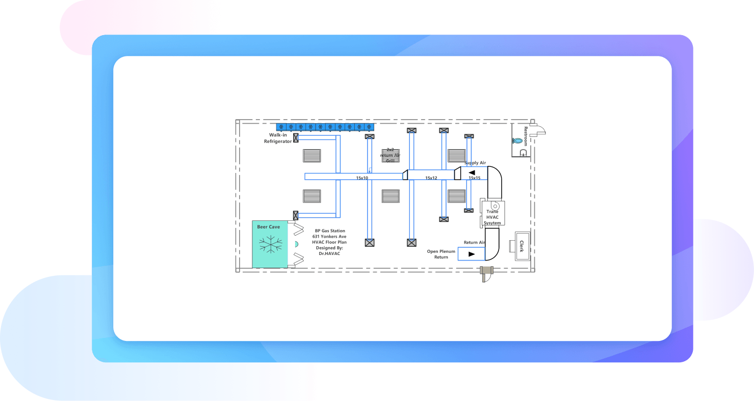
What exactly is an HVAC plan?An HVAC plan is a technical drawing that outlines the design and installation of heating, cooling, and ventilation systems in a building. It includes ductwork layouts, equipment locations, thermostats, and vents. These plans ensure that the indoor climate remains comfortable, air quality is high, and energy efficiency is maximized throughout.
-
What components are typically included in an HVAC blueprint?A comprehensive HVAC blueprint includes several key elements: furnace or air handler locations, outdoor condenser units, ductwork routing, and return air vents. It also specifies thermostat placements, exhaust fans, and refrigerant lines. Detailed labels for pipe sizes and airflow rates help installers execute the design accurately and maintain system performance.
-
What is the difference between a mechanical plan and an HVAC plan?While often used interchangeably, an HVAC plan is a specific subset of a broader mechanical plan. Mechanical plans can include plumbing, elevators, and other machinery. The HVAC plan focuses exclusively on thermal comfort and air quality, detailing the intricate network of ducts, fans, and units responsible for temperature and ventilation.
-
What role does ventilation play in a standard HVAC plan?Ventilation is a critical component that focuses on indoor air quality and moisture control. The plan specifies how fresh outdoor air is introduced and how stale air or pollutants are exhausted. Proper ventilation design prevents mold growth, removes odors, and ensures a constant supply of oxygen for a healthy environment.
-
How are ductwork sizes determined in an HVAC plan?Engineers determine ductwork sizes based on the volume of air needed to heat or cool a specific space. They use friction loss charts and velocity limits to ensure air moves quietly and efficiently. Correct sizing prevents noisy vents and ensures that every room receives the intended amount of conditioned air.
-
What are the common symbols used in an HVAC plan?HVAC plans use standardized symbols to represent various components like dampers, diffusers, and thermostats. For instance, a square with an "X" might indicate a supply duct, while specific lines represent refrigerant or gas piping. A legend is always included to help contractors accurately interpret these symbols during the installation.
Stop drawing. Start describing.
AI diagramming isn't just text-to-diagram.
AI now understands any input, fetches live data, adapts through dialogue, and works everywhere.
Free HVAC plan templates from EdrawMax