Free mechanical drawing software
Build welding diagrams, piping systems, and other mechanical drawings with EdrawMax. It is a user-focused software with a wide array of editable templates and vector symbols.

Why Use EdrawMax Mechanical Drawing Software?
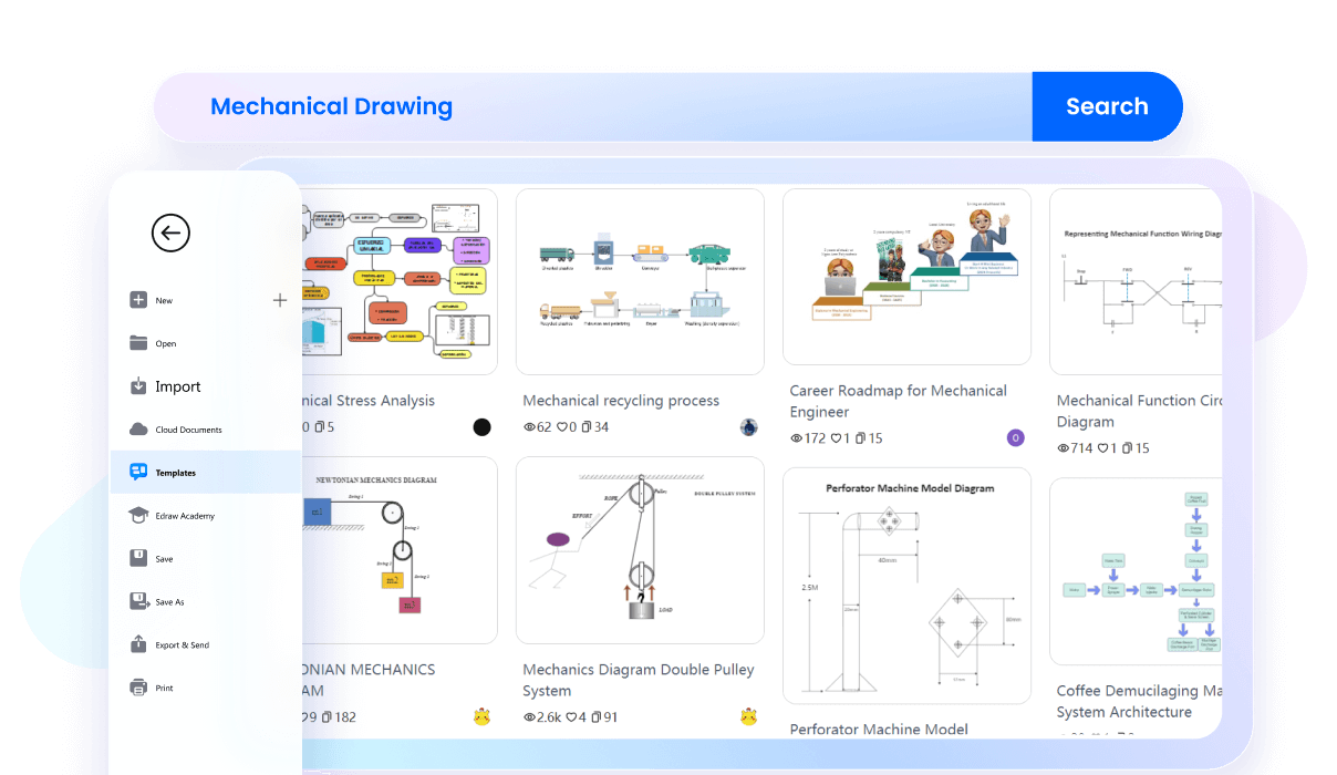
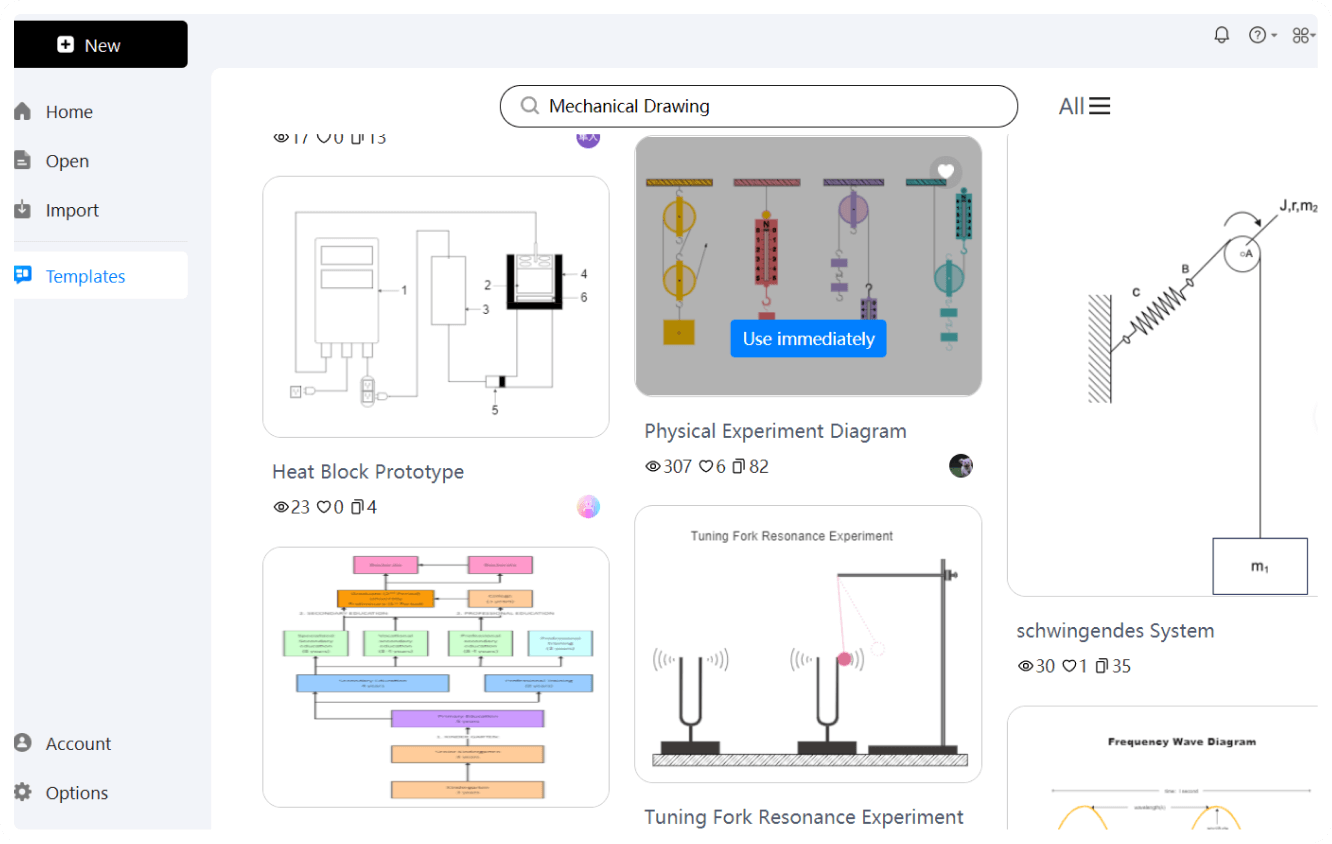
Save time and quickly start your design journey with the EdrawMax template community. Get creative inspiration from 2D and 3D design examples, posted by engineers, architects, and construction professionals. Find a suitable template, make small changes, and draft a unique mechanical drawing for your project.
Use our precision tools to decide the dimensions of your mechanical frameworks. You can manually control the design proportions or auto-size your page setups. It also supports all standard engineering and architectural sizes, including ANSI A, ISO A4, etc.
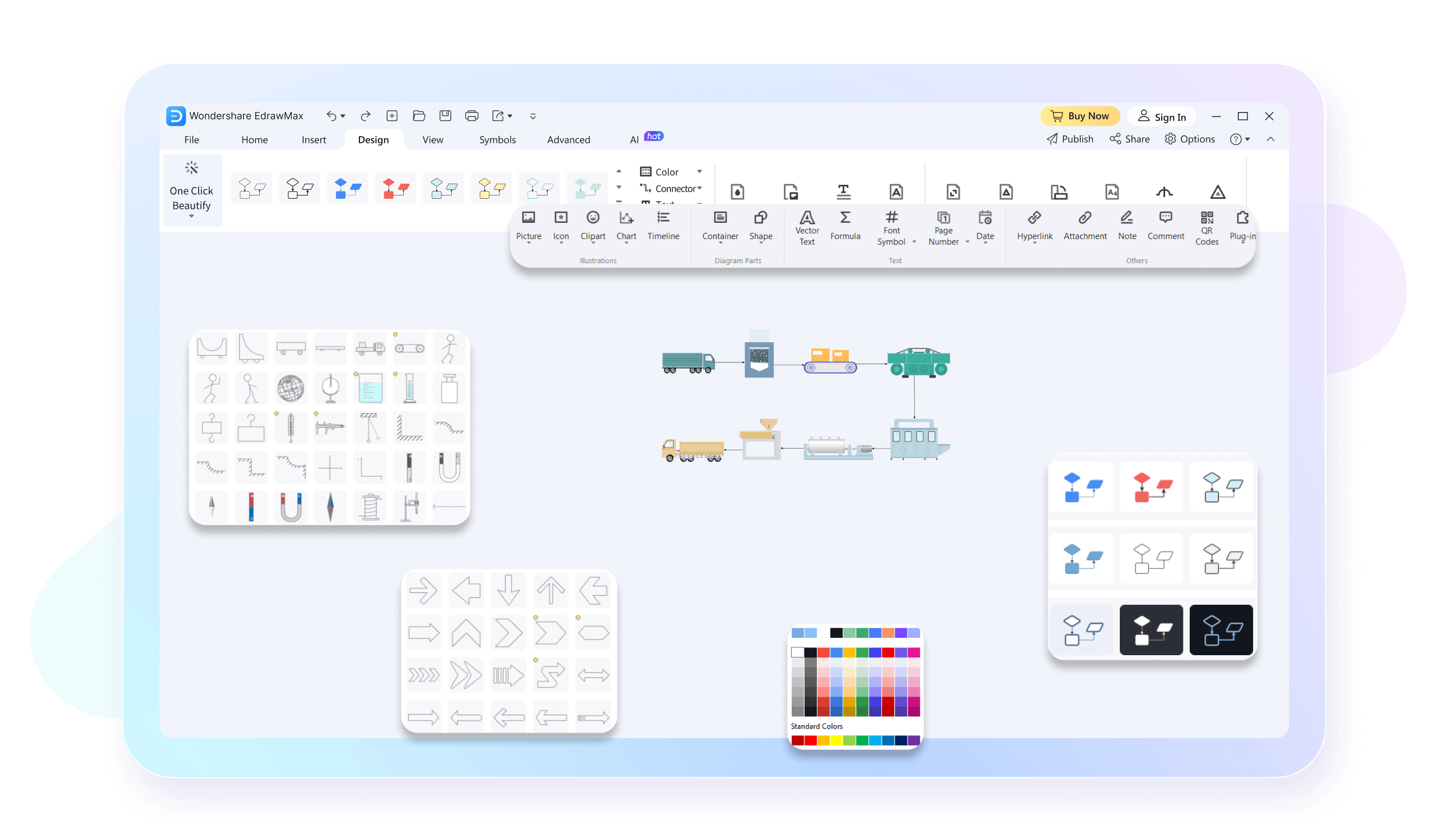
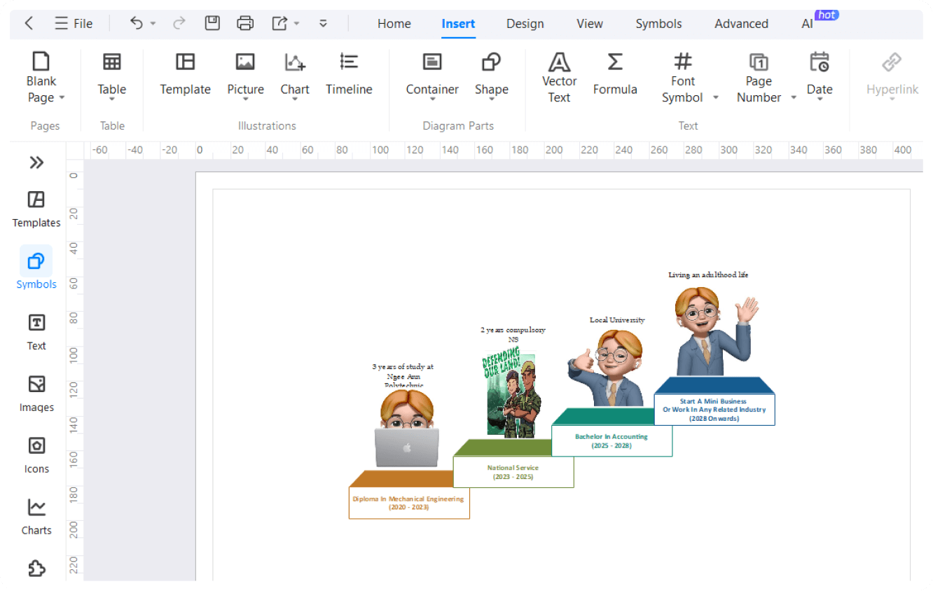
Start drafting 2D mechanical plans with EdrawMax’s clean interface and save yourself from hours of learning struggle. It supports an easily accessible toolkit, drag-and-drag design elements, and automatic formatting. Access our video tutorials when seem to counter an issue.
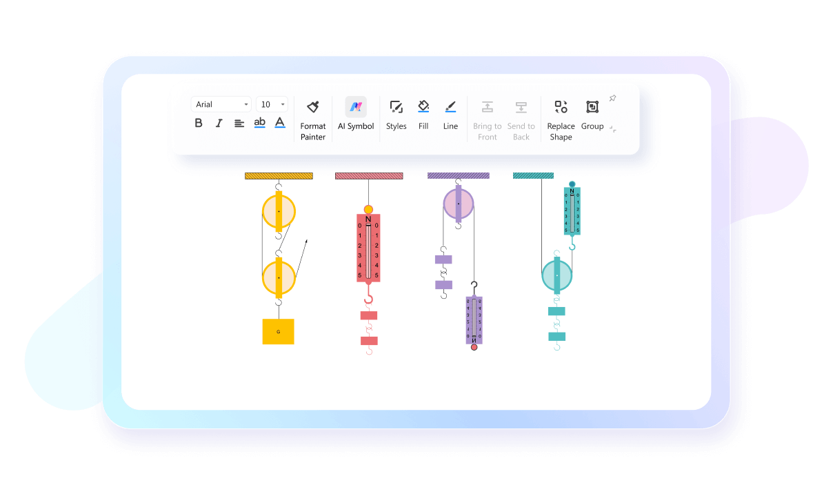
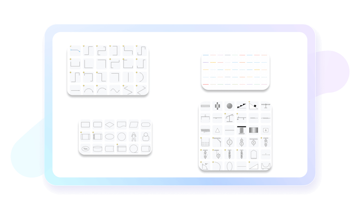
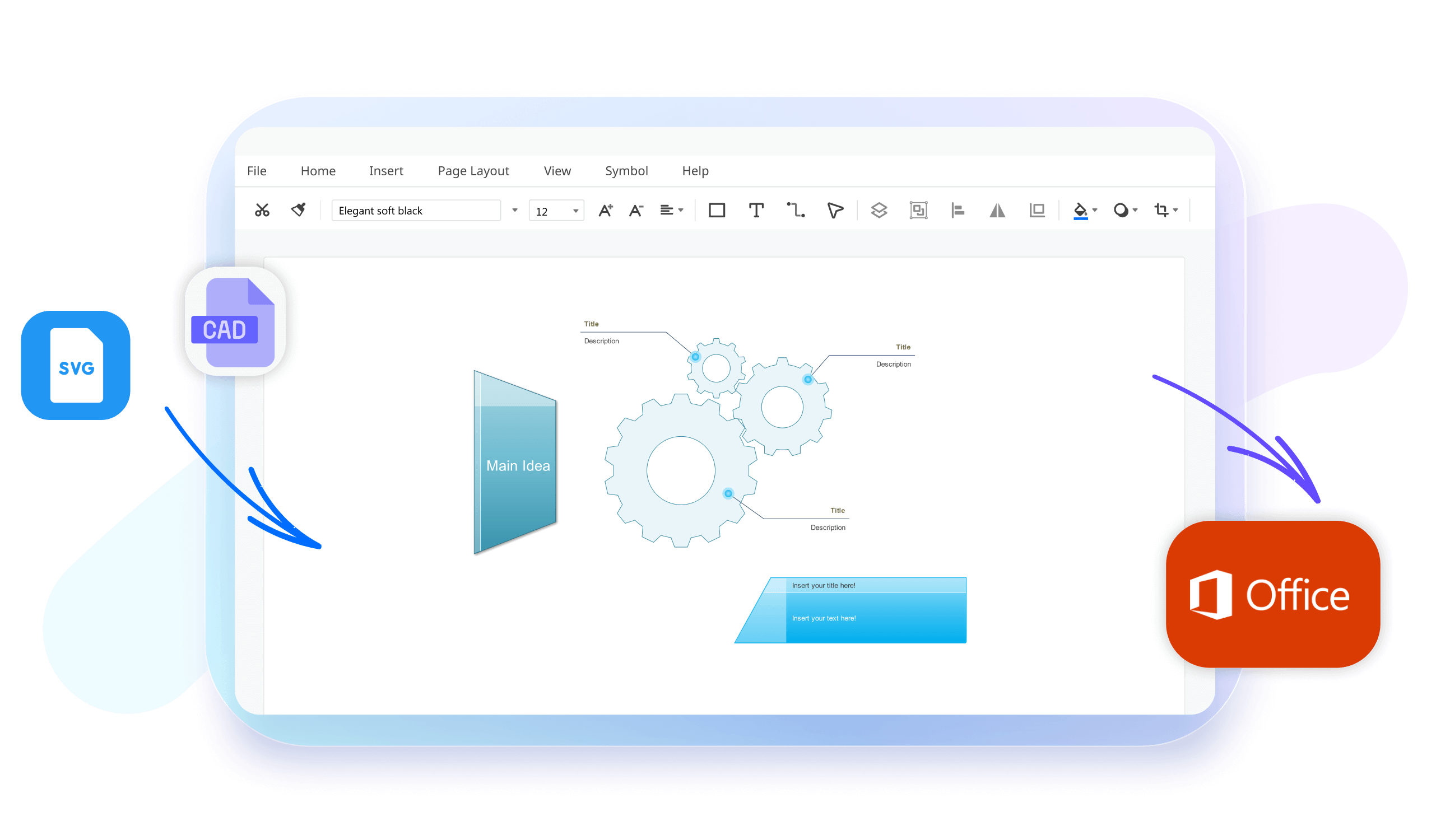
Our mechanical drawing software offers dozens of resizable industry-standard engineering symbols. Just add them to the canvas, and draft an accurate representation of your mechanical drawings. Plus, you are free to use preset styling options to personalize them with a few clicks.
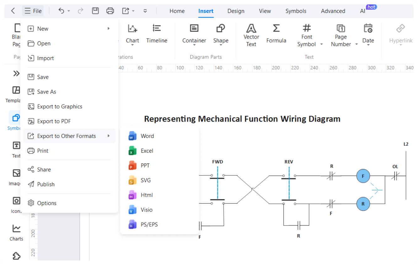
No more switching platforms to work with the engineering team. You can import your Visio and AutoCAD mechanical drawings and further edit them on the EdrawMax canvas. Reformat the structure, apply precision scales, and share the deliverable with key stakeholders.
How to Make a Mechanical Drawing in 3 Simple Steps
What our users say
More Mechanical Drawing Tools
Discover more AI-powered diagram makers to boost your productivity.
FAQs About EdrawMax Mechanical Drawing Tools
-
What is a mechanical drawing and why is it used?A mechanical drawing is a technical illustration used to communicate how an object functions or is constructed. It uses standardized symbols, scales, and perspectives to represent complex machinery or parts accurately. These drawings are essential for engineers and manufacturers to ensure precision during the production and assembly of mechanical components.
-
What are the primary types of views used in mechanical drawing?The most common views are orthographic projections, which include the top, front, and side views of an object. Additionally, isometric views provide a three-dimensional perspective, while sectional views reveal internal details by "cutting" through the part. These perspectives together provide a complete visual understanding of the object’s specific geometry.
-
What is the difference between first-angle and third-angle projection?These are methods for arranging orthographic views on a sheet. In first-angle projection, commonly used in Europe, the object is placed between the viewer and the plane. In third-angle projection, preferred in the United States, the plane is between the viewer and the object. Both systems effectively communicate three-dimensional shapes.
-
What are line types and what do they represent?Different line styles convey specific information in a drawing. For example, solid thick lines represent visible edges, while dashed lines indicate hidden features. Center lines show axes of symmetry, and dimension lines indicate lengths. Understanding these standardized "alphabets of lines" is crucial for correctly interpreting any technical mechanical drawing.
-
What are the standard symbols used in mechanical drawing?Symbols are used to represent specific features like threads, surface finishes, or welding requirements without using excessive text. Standards like ISO or ANSI define these symbols to ensure universal understanding among professionals globally. Using these icons saves space on the drawing and provides clear, standardized instructions for the manufacturing team.
Stop drawing. Start describing.
AI diagramming isn't just text-to-diagram.
AI now understands any input, fetches live data, adapts through dialogue, and works everywhere.
Free mechanical drawing templates from EdrawMax