


- What Is a Mechanics Diagram?
- Benefits of Using Mechanics Diagrams
- Symbols of Mechanics Diagrams
- How To Make a Mechanics Diagram Using EdrawMax?
- Examples of Mechanics Diagrams
- Why EdrawMax?
What Is a Mechanics Diagram?
Mechanics diagram is created to show the mechanical process in physical form. It is widely used by educators and instructors to provide students with a detailed and realistic description of the complex physical-mechanical mechanism so that students can know and comprehend physical principles and laws properly and improve their skills.
A mechanics diagram is a schematic representation of physics and engineering used to illustrate the applied forces, moments, and subsequent responses on a body under a given state.
Mechanics diagrams are used in many forms of mechanics problems to represent the forces and moments applied to a body and to quantify the resulting reactions. These diagrams are used both to assess the loading of individual structural elements and to quantify internal forces within the structure.
Benefits of Using Mechanics Diagrams
- Mechanical diagrams help simplify complex physics and science concepts into simpler visual illustrations.
- Mechanical diagrams help in visualising these complex concepts and make it easy for educators and professors to teach their students.
- It helps scientists or experts gain a deeper insight into complex science concepts and helps them form a mental picture.
Symbols of Mechanics Diagrams
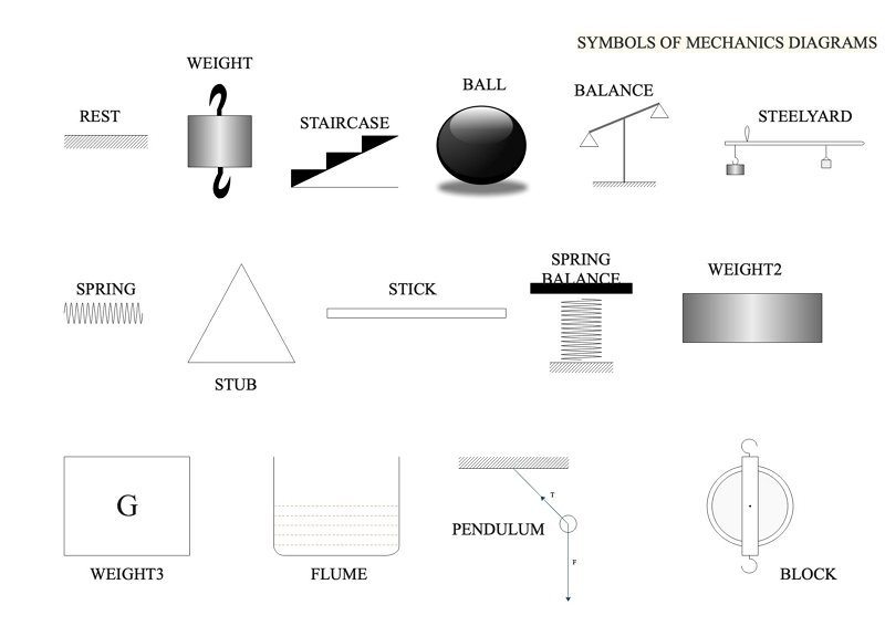
Rest
It represents an apparatus that measures the weight of an object or item.
Balance
Balance is designed to measure the weight of an item or object.
Steelyard
A steelyard is a weighing apparatus. Here the short arm is attached with the item that is to be weighed and the long arm has a weight that is moved until it balances.
Spring
A spring is an elastic device and an important component of mechanics diagram. As the use of spring is common in physics.
Weight 2
Weight 2 is the force extended on an object by gravity.
Weight 3
Weight 3 is the gravitational pull on the object.
Flume
A flume is a concept of hydrodynamics and is used in fluid dynamics.
Pendulum
The pendulum is represented by a weight suspended from a pivot so it can swing freely.
Block
Block symbolises the mounting for one or more pulley.
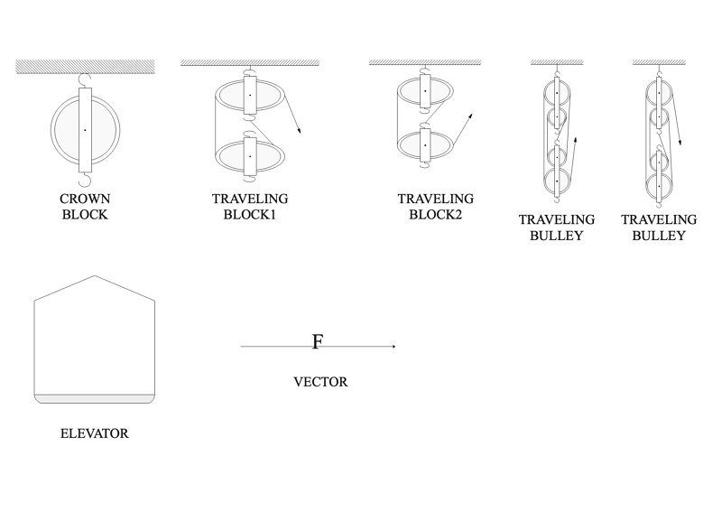
Crown block
A crown block represents the stationary section of a block and tackle which contains a set of pulleys or sheaves.
Travelling block 1
Travelling block 1 is the opposite of the crown block; it represents the freely moving section of a block and tackle that contains a set of pulleys or sheaves.
Travelling block 2
Travelling block 2 just like travelling block 1 is the freely moving section.
Travelling bulley
Travelling bulley is a simple machine consisting essentially of a wheel in which a pulled rope or chain can run to change the direction of the pull and thereby lift a load.
Elevator
Elevator works just like a pulley. They follow a simple mechanism of upward and downward acceleration.
Vector
A vector is a quantity that has both magnitude and direction. It can be represented with an arrow.
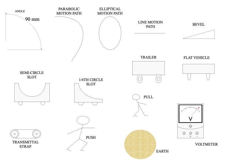
Angle
An angle is a shape, formed by two lines or rays diverging from a common point.
Angle
An angle is a shape, formed by two lines or rays diverging from a common point.
Parabolic motion path
A parabolic motion path is a path followed by a projectile.
Elliptical motion path
An elliptical motion path is the movement of an object in an oval path.
Line motion path
A line motion path is a movement in a linear manner.
Bevel
Bevel is a slant that symbolises the slant as seen in the diagram.
Semi-circle slot
A semi-circle slot is a depth in the shape of a semicircle.
1/4th circle slot
1/4th circle slot is a depth that is a quarter of a circle.
Transmittal strap
Transmittal strap acts as a belt with two-wheels for transmitting data/goods.
Push
Push is the physical act of pushing.
Pull
Pull is the physical act of pulling.
Voltmeter
A voltmeter is a device that measures the electric potential difference between two circuit points.
How To Make A Mechanics Diagram Using EdrawMax?
Step 1 - Open EdrawMax and select a blank canvas.
Step 2 - Once selected, your page will open, and you can create the diagram.
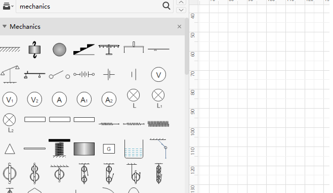
Step 3 - Under library, search for ‘mechanics,’ a wide range of symbols will appear.
Step 4 - Create your diagram, you can vector scale each symbol and make them fit any size.
Step 5 - Save and export your diagram to any file type you wish to. As EdrawMax is compatible with multiple file types.
Examples of Mechanics Diagrams
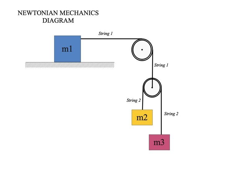
This diagram represents the Newtonian mechanics diagrams. The tension on m2 and m3 due to the string is represented effectively.
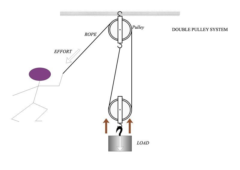
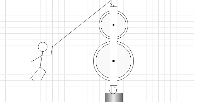
In a double pulley system, an individual pulls the rope from one side such that the load attached to the pulley can be lifted.
Why EdrawMax?
EdrawMax is a vector physical mechanics drawing software and includes lots of scientific illustration templates and examples which is easy to draw physical mechanics diagram.
- Customizable - Make the diagrams your own. Flexibility to use an extensive set of options to perfectly match the structure and design of your topic.
- Easy Formatting - The drag-n-drop interface and point-n-click editor have massively eased the formatting process.
EdrawMax is ideal for creating mechanics diagrams and any other diagrams with its easy-to-use interface and collection of symbols from a pulley to spring block.
AI Diagram Generator
Enter your prompt. Upload files if needed. Generate diagrams, charts, or slides instantly.


