




Electronic Symbols are widely used when we draw a circuit diagram. Through these symbols, we can easily recognize what exact electronic component we use here in this circuit. There are many types of electrical symbols such as standard symbols, ICES symbols, ladder diagram symbols. In this article, we are going to look over only at Ladder Diagram Symbols.
1. What are Ladder Diagram Symbols
These are special Symbols that are commonly used in industrial control logic systems. As they resemble a ladder with two vertical supply power and as many horizontal lines that represent control units that’s why they are called ladder diagrams.
Quick answer: Ladder diagrams represent control logic as horizontal rungs between two vertical power rails, using standardized contact, coil, timer, counter, and function symbols.
Ladder Diagram Symbols are the building blocks of ladder diagrams and they are also called ladder logic symbols. Every Ladder Symbol represents a certain ladder instruction. We use these symbols in the PLC programming that have been derived from relay logic control circuits. Check the common-used ladder diagram symbols below.
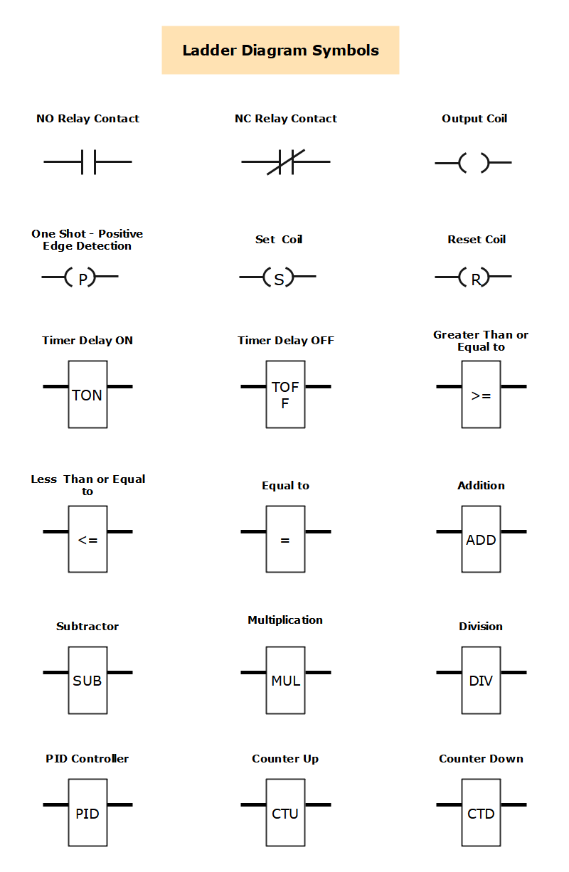
Source: EdrawMax Community
 Get 500 free AI tokens
2. Ladder Diagram Symbols Explained
Ladder diagrams symbols are the basic building blocks of a Ladder Circuit Diagram and these symbols are used in the PLC Programming. Here are some Symbols which are given below with their names and we also provide a symbol table, there you can find all ladder symbols with their names and their description.
| Symbol | Name | Description |
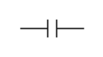 | Normally Open Contact (NO) Symbol | Its operation is very simple. When the condition is true then the contact is closed and output logic flow is enabled. When the condition is FALSE then the contact is OPEN and output logic flow is blocked. |
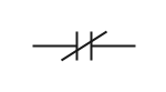 | Normally Closed Contact (NC) Symbol | When the condition is true then the contact is OPEN and output logic flow is blocked. And when the condition is FALSE then the contact is CLOSED and output logic flow is enabled. The NC contact symbol operation is nothing but just the opposite to the NO contact symbol. |
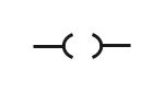 | Output Coil Symbol | When the input condition is true then the output is ON. And when the input condition is false then the output is OFF. |
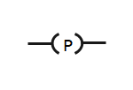 | One Shot Symbol– Positive Edge Detection | When the input condition transitions from FALSE to TRUE then the output is ON, for the time taken to do one PLC scan. |
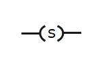 | Set Coil Symbol | When the input condition transitions from false to true then the output is set ON and once the output is set ON, it stays ON, even if the input condition goes FALSE. |
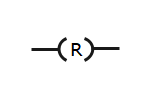 | Reset Coil Symbol | When the input condition is true then the output is reset to OFF. And when the input condition is false it has no effect on the output. The SET and RESET coils can share the same variable address and therefore work hand in hand. |
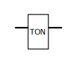 | Timer Delay on Symbol | When the input condition is true then the timer begins. And when the present time set point has been reached the output turns ON. If the input condition goes FALSE, at any stage, the timer stops and the output turns OFF as well. |
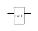 | Timer Delay off Symbol | When the input condition is true then the output turns ON. Then if the input condition goes false the timer begins and when the preset time set point has been reached the output turns OFF. If the input condition goes TRUE, at any stage, the timer stops and the output turns ON as well. |
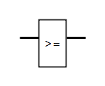 | Greater than or Equal to | When the two inputs comparison is true then output is true otherwise false. |
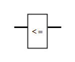 | Less than or Equal to | When the two inputs comparison is true then output is true otherwise false. |
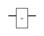 | Equal to | When two inputs are equal then output are true. |
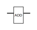 | Adder | Adder is used to add two or more inputs. |
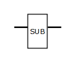 | Subtractor | Subtractor is used to subtract one value from the other one. |
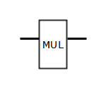 | Multiplication | Multiplication block is used to multiply two or more values. |
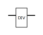 | Division | Division block is used to divide two values. |
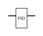 | PID Controller | PID Controller is used to control the process value. The process variable is measured from the primary element (Input) and the output is manipulated to maintain the process variable value at the set point input value. The Proportional, Integral and Derivative input values are tune to increase the performance of controlling. Which is done according to process requirements. |
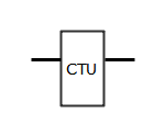 | Counter Up | When input is True from False then counter increases 1 value from the last stored value. When this stored value reaches the preset value, the output will go True and the stored value is set again to 0. |
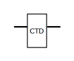 | Counter Down | When input is True from False then counter decreases 1 value from the last stored value. When this stored value reaches 0 value, the output will go True and the stored value is set again to preset value. |
3. Tips for Using Ladder Diagram Symbols
As we discussed the Electrical Ladder Symbols above and provide all the information about it. Ladder diagrams also help us to formulate the logic expressions in a graphical form. These symbols are graphical notations that can easily be noted. Here are some tips for using ladder diagram symbols.
3.1 Use a Professional Ladder Diagram Tool
Open EdrawMax Online and go to the symbols library and select electrical symbols and go to the ladder symbols. 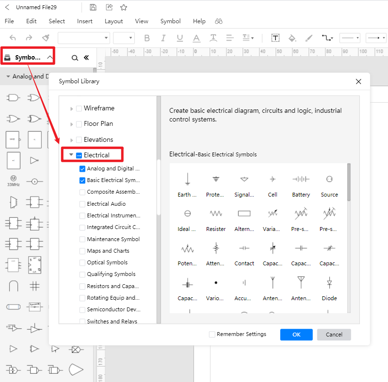
Get 500 free AI tokens
3.2 Create Electrical Ladder Symbols by Yourself
EdrawMax Online has a vast electrical symbols library, but as we already discussed, you can also add your individualized icons based on your requirements. Import your symbols in SVG, VSSX, and other formats easily using the import tool. Go to the library option on the sidebar and click on the import icon. Different tabs in the new pop-up window will show you selection tools. 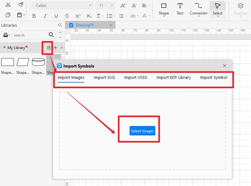
4. Conclusion
As we discussed the Electrical Ladder Symbols above and provide all the information about it, hope you can have a further understanding now. You can also find all circuit diagram templates from the EdrawMax Template Community.
AI Diagram Generator
Enter your prompt. Upload files if needed. Generate diagrams, charts, or slides instantly.


What do normally open and normally closed symbols mean in ladder logic?
A normally open contact passes logical continuity when its condition is true; a normally closed contact passes continuity when its condition is false. They describe logic state, not necessarily a device's physical resting position.How do you read a ladder diagram?
Read each rung from left to right and the diagram from top to bottom. Follow the conditions leading to the output coil or instruction at the right side of each rung.



 (AI & Web)