




P&ID symbols are graphical conventions used in piping and instrumentation diagrams to represent process equipment, piping, valves, instruments, control functions, and connections. They help engineers, operators, technicians, and contractors read how a process is intended to work without relying on long written descriptions.
No single symbol sheet should be treated as universal in every project. Instrumentation and control conventions are commonly aligned with standards such as ANSI/ISA-5.1-2024, while organizations and projects may define approved variations in their own legends. Treat the project legend as the final reference when a symbol differs from a general symbol library.
Quick lookup: identify the symbol family first, then check the tag, line or connection type, actuator, and project legend. This sequence helps you move from a general symbol category to the drawing-specific meaning without treating a familiar shape as universal.
In this article
1. What Are P&ID Symbols?
P&ID symbols provide a compact visual language for process documentation. A complete P&ID can show equipment such as pumps and vessels, the lines that connect them, valves that control or isolate flow, instruments that measure process variables, and control functions that act on the process.
At a glance: P&ID symbols represent equipment, piping and signal lines, valves, instruments, and control functions on a process drawing. ANSI/ISA-5.1-2024 provides a standardized system for instrumentation and control symbols and identification, but an actual project legend still governs approved symbol variants and tag conventions for that drawing.
| Category | What it represents | Typical examples |
|---|---|---|
| Piping and line symbols | Process and utility connections | Process lines, signal/connection lines, flanges, reducers, connectors |
| Pumps | Equipment that moves fluids | Centrifugal, positive-displacement, vacuum pumps |
| Valves | Flow isolation, throttling, direction, or protection | Gate, globe, ball, check, control, relief valves |
| Vessels | Containers for process fluids | Tanks, drums, columns, separators |
| Heat exchangers | Heat transfer between process streams | Shell-and-tube, plate, air-cooled exchangers |
| Compressors | Gas compression and movement | Centrifugal, reciprocating, rotary compressors |
| Instrumentation | Measurement, indication, control, and alarms | FT, PT, TIC, LIC, control loops |
How to read a P&ID symbol at a glance: identify the symbol category, read the tag or functional letters, trace the relevant line or signal type, check any actuator or equipment details, and verify the final meaning against the project legend.
2. What Do the Main P&ID Symbol Categories Mean?
2.1 Piping P&ID Symbols
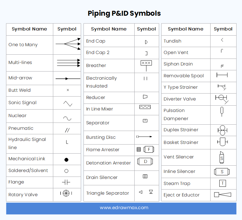
Piping symbols show how process and utility streams move between equipment. Read the line type, direction, connections, reducers, flanges, fittings, and line identification together; the exact line conventions can vary by project.
2.2 Pump P&ID Symbols
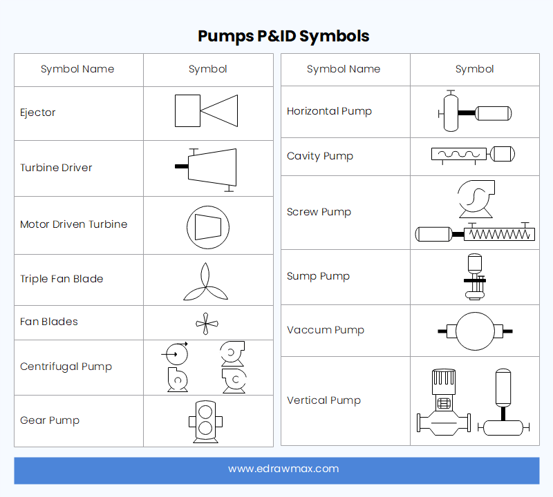
Pump symbols identify equipment used to move liquids or create pressure differences. The symbol shape helps distinguish pump types, while equipment tags and nearby notes provide the project-specific identity and service.
2.3 Valve P&ID Symbols
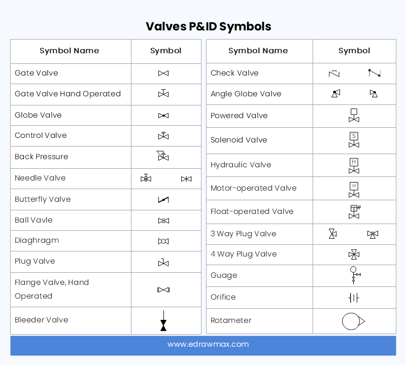
Valves should not be reduced to only two categories. A P&ID may show manual isolation valves, check valves, control valves, pressure-relief devices, and valves with different actuator types. Interpret both the valve body symbol and its actuator or control indication.
2.4 Vessel P&ID Symbols
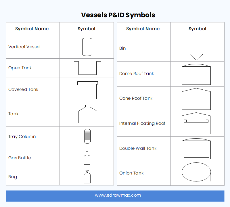
Vessel symbols represent tanks, drums, columns, separators, reactors, and related process containers. Orientation and internal details may be shown when they are important to process understanding.
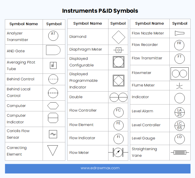
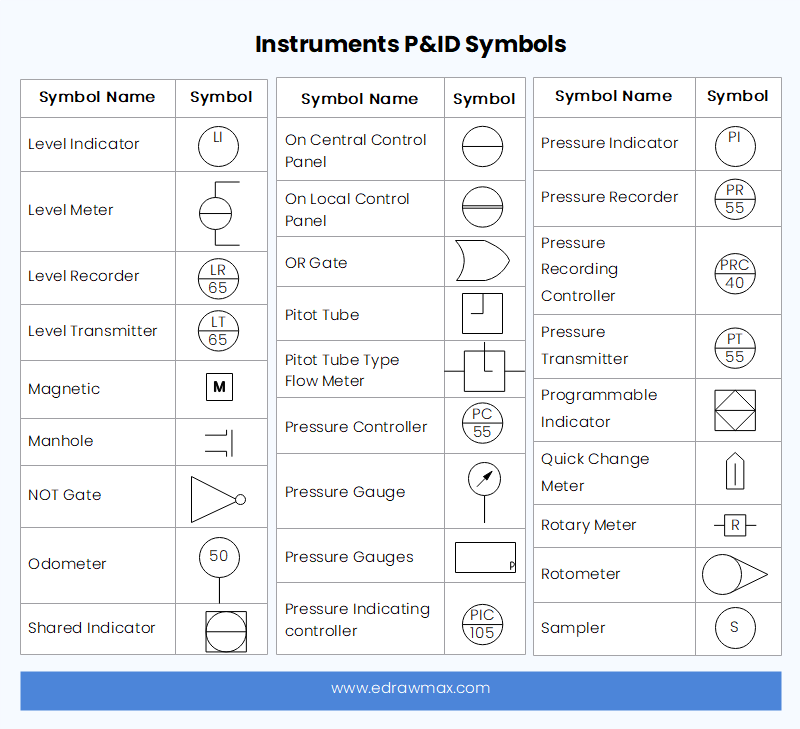
2.5 Instrumentation P&ID Symbols
Instrumentation symbols show measurement and control functions. A tag such as FIC is read by interpreting its letters in context: “F” commonly denotes flow, “I” indication, and “C” control. The instrument bubble, line treatment, tag number, and project legend together tell you where the function is implemented and how it relates to the control loop.
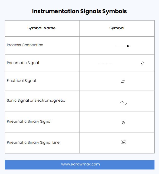
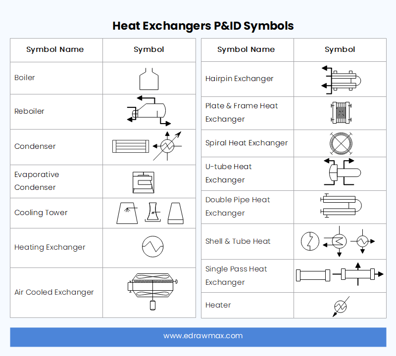
2.6 Heat Exchanger P&ID Symbols
Heat exchanger symbols identify equipment that transfers heat between streams or between a process stream and a utility. The P&ID should be read with the connected lines and tags to understand which fluid goes where.
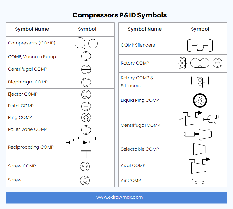
2.7 Compressor P&ID Symbols
Compressor symbols represent equipment that raises gas pressure or moves gas through the process. The specific compressor type, driver, auxiliaries, and control elements may be shown separately depending on the drawing scope.
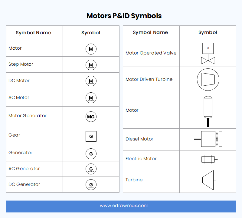
2.8 Motor and Equipment Symbols
Motor symbols may be connected to pumps, compressors, fans, or other driven equipment. Do not infer operating logic from the motor symbol alone; use the tag, control connections, notes, and related documentation.
2.9 Instrument Symbols and Bubbles
Instrument bubbles combine graphical location conventions with letter-based functional identification. Because drawing practices can differ, avoid interpreting a horizontal or dashed line in isolation. Use the applicable ISA convention and the project legend to determine whether a function is field-mounted, panel-mounted, shared-display, inaccessible, or implemented in a control system.
3. How Do You Read P&ID Instrument Tags?
Read an instrument tag in layers instead of guessing from one letter. First identify the process variable, then the function, then the loop or tag number. For example, FIC-101 commonly indicates a flow-indicating controller in loop 101. A related FT-101 may be the flow transmitter that supplies the measurement, while an FCV-101 may be the final control valve. Exact naming still depends on the project convention.
- Identify the measured variable. F often means flow, P pressure, T temperature, and L level.
- Read the functional letters. I commonly means indicator, T transmitter, C controller, S switch, and A alarm.
- Match the loop number. Instruments that share a loop number are usually functionally related.
- Trace signal lines. Follow the drawing's signal conventions to see how sensing, control, and final elements interact.
- Check the legend. Project-specific symbols and tag rules override assumptions.
4. What Are Common P&ID Abbreviations?
| Abbreviation | Common meaning |
|---|---|
| FC | Flow Controller |
| FCV | Flow Control Valve |
| FE | Flow Element |
| FI | Flow Indicator |
| FIC | Flow Indicating Controller |
| FT | Flow Transmitter |
| LC | Level Controller |
| LIC | Level Indicating Controller |
| LT | Level Transmitter |
| PCV | Pressure Control Valve |
| PI | Pressure Indicator |
| PT | Pressure Transmitter |
| TIC | Temperature Indicating Controller |
| TT | Temperature Transmitter |
| MOV | Motor-Operated Valve |
| AOV | Air-Operated Valve |
These are common interpretations, not a replacement for the legend or governing standard used on a specific drawing.
5. What Is the Difference Between a P&ID and a PFD?
| Aspect | PFD | P&ID |
|---|---|---|
| Main purpose | Shows major process flow and key equipment | Shows detailed piping, instrumentation, valves, and control functions |
| Detail level | Higher-level process view | Detailed engineering and operational view |
| Typical use | Process understanding and design overview | Design, review, operation, maintenance, and troubleshooting |
For formal instrumentation and identification conventions, refer to the ISA-5 standards family. Project-specific legends can still define approved variations, so use the governing project documentation when interpreting an actual drawing.
6. Tips and FAQs for Using P&ID Symbols.
- Always start with the drawing legend and revision status.
- Trace the process from equipment to equipment instead of reading isolated symbols.
- Match instrument tags by loop number to understand control relationships.
- Do not assume every company uses identical symbol variants.
- Use current project and industry standards when creating or revising engineering documentation.
Are P&ID symbols universal?
They are standardized to a significant degree, but not perfectly universal. ISA standards provide widely used conventions and explicitly allow some alternative symbolism methods. Company and project legends can add further conventions.
What does FIC mean on a P&ID?
FIC commonly means Flow Indicating Controller: F for flow, I for indication, and C for control. The tag number identifies the loop or function within the project.
What are the main P&ID symbol groups?
The main groups usually include piping and line symbols, pumps, valves, vessels, heat exchangers, compressors, motors or other equipment, and instrumentation. The exact set and graphical convention can vary, so a project legend remains the final reference for an actual drawing.
What should I check before using a symbol library?
Confirm that the library matches the standard and project conventions you are required to follow. A convenient symbol is not automatically the correct symbol for every organization.
 Get 500 free AI tokens
Reference: ANSI/ISA-5.1-2024: Instrumentation and Control – Symbols and Identification.
AI Diagram Generator
Enter your prompt. Upload files if needed. Generate diagrams, charts, or slides instantly.





 (AI & Web)