PID (Proportional Integral Derivative) Controller is a device or instrument used in industrial levels to regulate different parameters, including pressure, flow, temperature speed, etc. These controllers are widely used and are independent of the operators as they work on the set values for these parameters.
In this guide, we will talk about the PID Controller's working through its block diagram. It will cover all the benefits, uses, and working of the PID Controller. You will also learn how to make a PID Controller block diagram through different methods.
In this article
Part 1. What is a PID Controller?
PID Controller is an essential device used to control or maintain different parameters around the set values by the operator. It is used to control the for multiple purposes like mixing chemicals in a correct proportion, flowing water into the container at set values, keeping the temperature of the machine or a closed room at a specific value, etc. PID Controller uses a control loop feedback to sense this parameter's current and set values and provides an output favourable to the process.
Having these Controllers at Industrial Levels is quite handy as it reduces the operator's workload. Most home appliances also use these controllers, but they are in smaller sizes. It also displays the digital values of these parameters as well.
Why use a block diagram of the PID Controller?
A block diagram for the PID Controller serves different benefits for us. It is used to see the working methodology of the system and helps engineers understand the purpose of the system so that they can improve it if changes are needed.
A block diagram can help us know the components used in a machine or device. It helps us get an idea of whether the components we used match our requirements or not. At the same time, it also helps us find the irregularities in a device.
Block diagrams are beneficial in electronics, software development, hardware, etc. They help us with finding technical issues and save a lot of time.
Part 2. Block Diagram for PID Controller
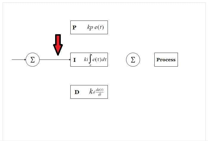
Here is the block diagram for the PID Controller.

The Block diagram of the PID Controller shows it working in a closed-loop action. In such a close loop controller, the efficiency of our work is outstanding. In the case of an open loop system, the system runs for a specific time and doesn't focus on the desired results.
For example, when we turn on a dryer, it runs over a period, and it is set and turned off after that time, irrespective of whether the clothes are dry. When a Closed-loop dryer is seen, a sensor is set to check whether moisture is present in the clothes. If there is any moisture left, the dryer will not stop working. When the clothes are completely dried out, the dryer will stop and provide output (dry clothes).
PID Controller combines three basic terms, i.e. Proportional, Integral and derivatives. So, there are three modes of the device. Let's check them out one by one.
Proportional (P) Response
As shown in the block diagram for the PID Controller, The Proportional (P) value is the value of the error, usually known as a steady-state error. When this value is large, the output will be large, and the system will behave abnormally. So, a P Controller doesn't fulfil our needs alone.
Integral (I) Response
The integral response controller keeps the steady-state error as low as possible. The Integral action continues until this steady-state error is zero and the output is the same value we set for our parameter.
Derivative (D)Response
This Controller is not used alone as well. The integral Controller keeps the steady state error to zero, but there is always a constant error at higher speeds. The derivative Controller keeps this constant error in check and keeps the output value to set value, neglecting any kind of constant errors.
Part 3. How do you make a block diagram for a PID controller on EdrawMax?
Block diagrams offer value to engineers and let them know the insights of a system. They are used for numerous benefits ranging from understanding a system to improvements. Block diagrams for PID Controllers are drawn through these two methods.
Method 1: Start From Scratch
In this method, you need to draw all the components by yourself. It is an easy method—you must drag and drop elements on the canvas. You can find all the symbols and equations to complete your diagram. Let's discuss this method.
Here are a few steps you need to draw a block diagram.
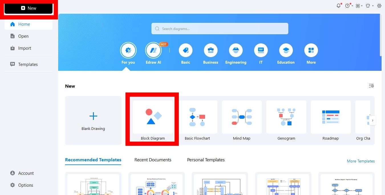
Step 1: Download EdrawMax and open it. Click New > Block Diagram.
Step 2: You will find symbols and components on the left-hand side of the screen. Check if all the components are available there to draw your diagram.
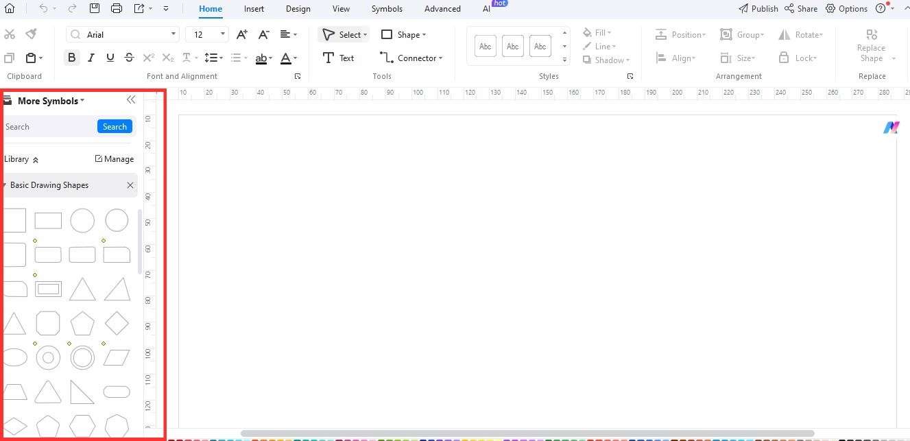
Step 3: Drag components or blocks from this symbol bar on the canvas.

Step 4: Label all the blocks and keep them in good symmetry.
Step 5: Draw relationship lines among the blocks and other components.
Step 6: Add colors to the block and elements in the block diagram.
Step 7: Add a background to make your design look better. You are allowed to use your background and the backgrounds given in EdrawMax.
You have completed the diagram. It is as simple as it can get.
Method 2: Starting with a Template
A template makes your work easier. You don't need to drag and drop components; all you need to do is make changes in the already given template and put your values and labels to make a diagram of your own. All you need to do is to follow these steps.
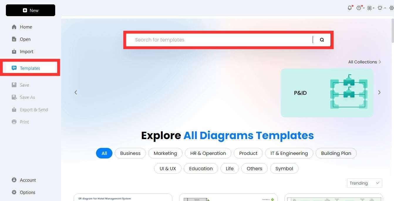
Step 1: Open EdrawMax, click Templates, and enter block diagrams in the search bar.
Step 2: You will see a lot of block diagram samples to pick from.
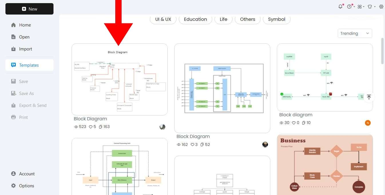
Step 3: Pick a diagram and click Use immediately.
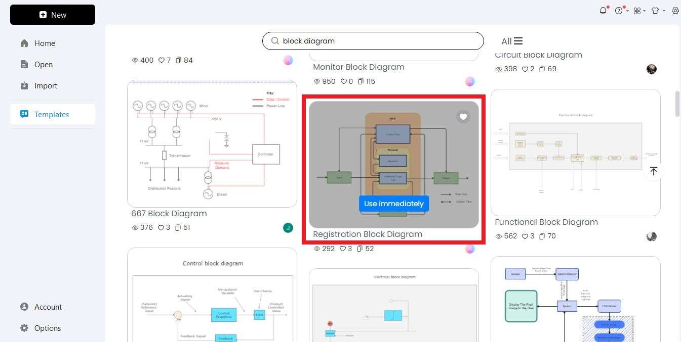
Step 4: Use this template and make your block diagram in minutes.

That’s it. You can edit this template and make changes according to your requirements.
Part 4. PID Controller Working & Its Applications
The PID Controller works in a closed loop and precisely keeps the set parameter values. There are several applications of these PID Controllers. Let's check a few of those.
- In industries where huge temperatures are acquired to melt raw materials, PID controllers help us there. It becomes difficult to maintain the temperature of the furnace and the temperature of the materials needed at the output. In such a case, the PID Controller enters the act and helps achieve the required temperature. The heat is sensed through a fan, and a PV signal is applied through the PID controller. A PV signal is applied, and a derivative controller stabilizes the heat of the furnace and the required materials at the output.
- PID Controllers are used in water flow systems, pH, and speed control systems.
- Pharmaceutical Companies use PID controllers to maintain the temperature of the medicine at certain levels.
- Humidity is also controlled through PID controllers in places like food factories, where they need an optimal temperature to preserve the food.
Conclusion
PID Controllers are useful devices that help us maintain temperature, pressure, flow, speed, and humidity. They are also used in smaller home appliances as well. We have discussed all the relative things about a PID Controller through its block diagrams. These block diagrams for PID Controller serve more benefits and help anyone understand and change the model when needed.
If you need to make such block diagrams for your systems, it is easier to draw them through EdrawMax. You can find templates and all the elements needed to make those diagrams. So, give it a try and have a lifetime beat experience.
[没有发现file]