UML diagrams serve as visual representations of software systems, illustrating their structure, behavior, and relationships. They are invaluable tools for software engineers, designers, and stakeholders to conceptualize, communicate, and analyze complex systems. With various types, such as class, sequence, and activity diagrams, UML provides a standardized language for depicting software designs, aiding in the development process from conceptualization to implementation.
In Miro, a collaborative online whiteboard platform, creating UML diagrams becomes an interactive and seamless process. UML diagram in Miro offers a range of features tailored for diagramming, including customizable templates, shape libraries, and real-time collaboration tools. Continue reading below to learn more.
In this article
Part 1: How to Create a UML Diagram Using Miro’s Template
Creating a UML diagram using Miro's template is a straightforward process to streamline your workflow. Follow these steps to get started:
Step 1: Access Miro's Template Library
Launch Miro and navigate to the template library. Search for "UML diagram" or browse the software engineering category for the relevant template.
Step 2: Select the UML Template
Once you've found the UML template, click on it to open a new board with the pre-built structure for your diagram.
Step 3: Customize the Diagram
Modify the template to fit your specific requirements. Add or remove elements, adjust sizes, and rearrange components to reflect your software design accurately.
Step 4: Collaborate in Real Time
Invite team members to collaborate on the UML diagram in real time. Miro's collaborative features allow multiple users to work together, providing valuable input and insights.
Step 5: Share and Iterate
Once the UML diagram is complete, share it with stakeholders for feedback. Use Miro's sharing options to distribute the diagram via email, link, or embedding.
Part 2: Advantages of Using a UML Diagram Template
After creating a UML diagram template in Miro, users gain numerous benefits that streamline the diagramming process and enhance the quality of their software design representations. These advantages range from time-saving features to ensuring consistency and providing valuable guidance throughout the diagram creation process.
Let's delve into these advantages in detail:
Time Efficiency
By providing a pre-built structure, templates save significant time and effort that would otherwise be spent creating the diagram from scratch. This allows users to focus more on the content and details of their software design rather than the initial setup.
Consistency
Templates ensure uniformity in the layout and notation of UML diagrams throughout a project or team, promoting clarity and coherence. Consistent presentation enhances readability and comprehension, making it easier for stakeholders to understand and contribute to the software design process.
Guidance
Templates often come with built-in prompts or guidelines, offering valuable assistance to users in accurately representing their software designs. These prompts can include suggestions for which UML elements to include, how to arrange them effectively, and best practices for labeling and notation. Such guidance helps users navigate the complexities of UML diagramming, especially for those less familiar with the notation or specific diagram types.
Additionally, users can explore alternative tools such as EdrawMax for creating UML diagrams. EdrawMax offers similar functionality and collaborative features for visualizing software designs. It provides a comprehensive platform with an intuitive interface and robust capabilities, empowering users to express their software design concepts effectively.
Part 3: Utilizing EdrawMax as a Tool for Creating a UML Diagram
EdrawMax is a versatile UML diagram tool for creating UML diagrams in the easiest steps.
It offers users a comprehensive platform to visualize and effectively communicate their software designs. Boasting a user-friendly interface and robust features, EdrawMax emerges as a formidable alternative to Miro, catering to the needs of professionals and beginners in streamlining the diagramming process.
Its intuitive design empowers users to navigate through complex software structures with ease, while its extensive toolkit facilitates the creation of precise and visually appealing UML diagrams. Whether for collaborative projects or individual endeavors, EdrawMax is a reliable companion, providing the necessary tools and functionalities to bring software design concepts to life.
Key Features of EdrawMax for UML Diagramming:
To streamline the process of UML diagramming, EdrawMax offers a rich array of features to empower users to express their software design concepts with precision and clarity. Let's delve into the key features that position EdrawMax as an indispensable tool for UML diagram creation:
Extensive UML Library
EdrawMax boasts an extensive library of pre-designed UML shapes and templates, providing users with various options to accurately represent different aspects of their software designs.
Advanced Customization Options
Users can easily customize their UML diagrams with advanced formatting options, allowing them to easily tailor their diagrams to specific project requirements.
Real-Time Collaboration
EdrawMax facilitates seamless teamwork with its collaboration features, enabling users to collaborate in real-time, exchange feedback, and make revisions together.
Part 4: How to Create a UML Diagram in EdrawMax
Creating UML diagrams in EdrawMax is a straightforward process that empowers users to visualize their software designs effectively. Follow these simple steps to create your UML diagram:
Step 1: Launch EdrawMax
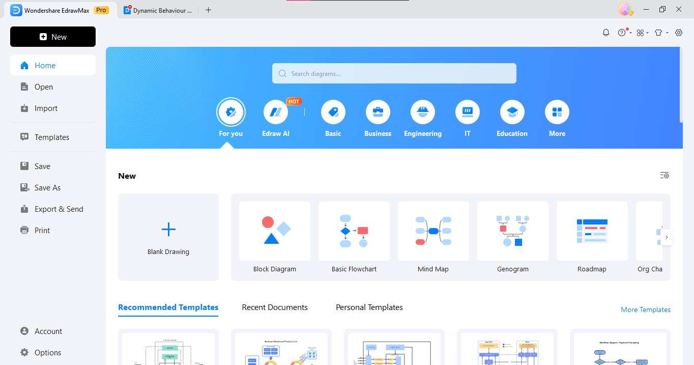
Open the EdrawMax application on your device.
Step 2: Select UML Diagram
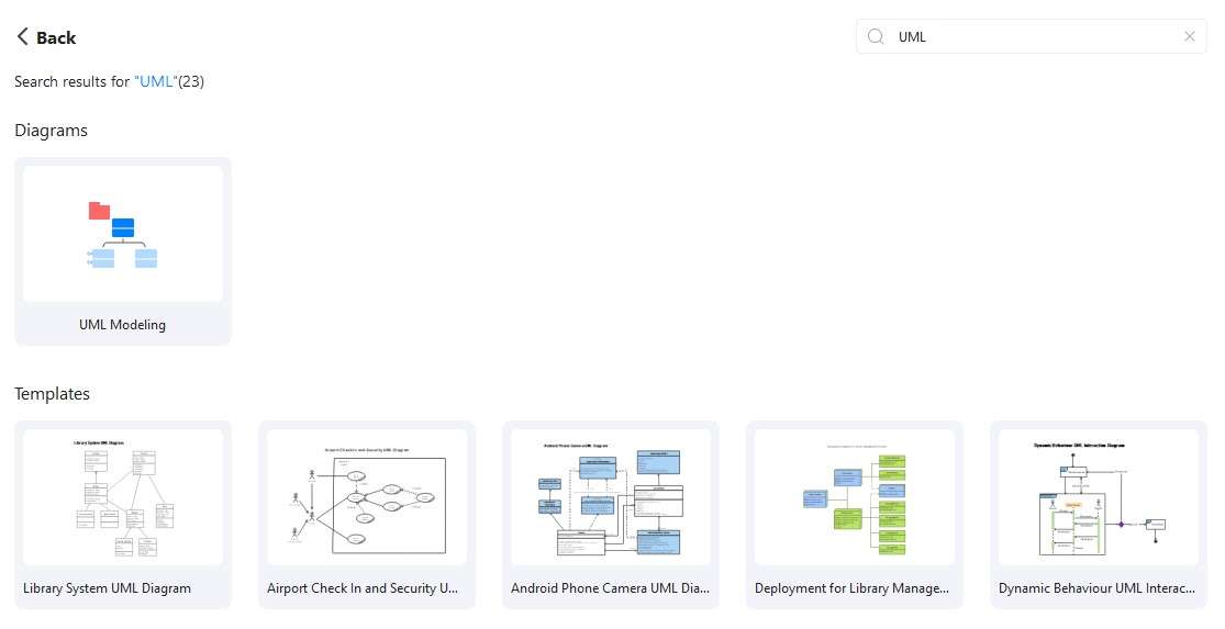
You can create a new UML diagram from the template gallery or select a blank canvas to start from scratch.
Step 3: Add UML Shapes
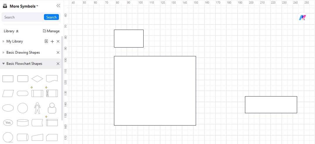
Browse through the extensive library of UML shapes and drag and drop the desired elements onto your canvas.
Step 4: Connect Elements
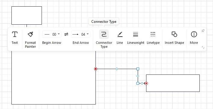
Establish relationships between different UML elements using connectors or lines, accurately depicting the connections within your software design.
Step 5: Add Details

Provide detailed descriptions or labels for each UML element to clarify its purpose and functionality within the software design.
Step 6: Customize and Format
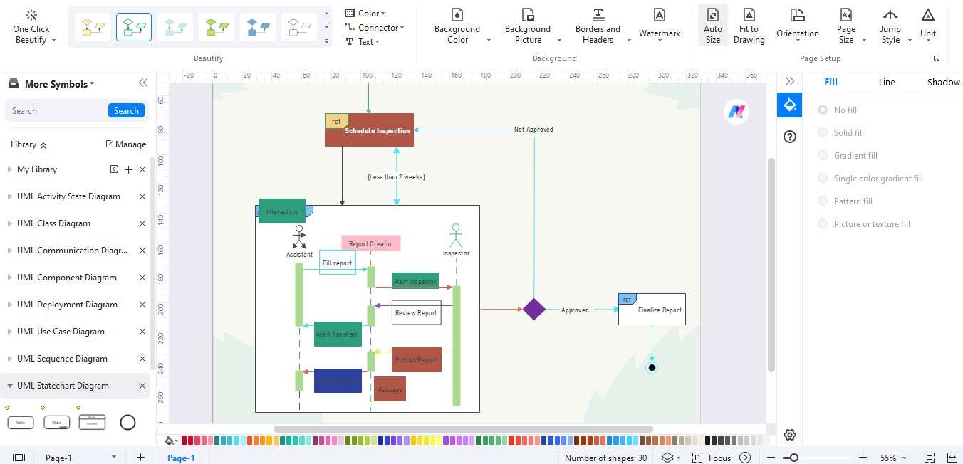
You can customize the appearance of your UML diagram by adjusting colors, fonts, line styles, and other formatting options to enhance clarity and visual appeal.
Step 7: Collaborate and Share
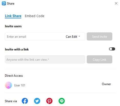
Invite collaborators to review and contribute to your UML diagram in real-time, facilitating seamless teamwork and feedback exchange.
Step 8: Save and Export
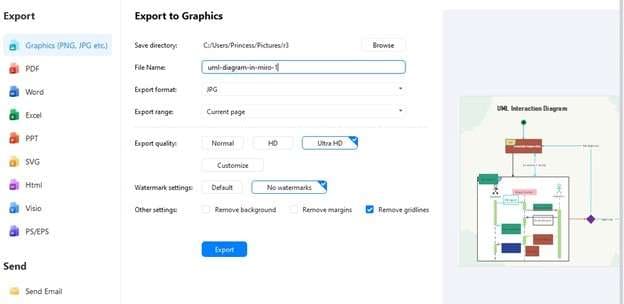
You can save your completed UML diagram within the EdrawMax application and export it in your desired file format for sharing or further use.
By following this step-by-step guide, users can effectively utilize EdrawMax to create professional-quality UML diagrams, empowering them to visualize and communicate their software designs precisely and clearly.
Conclusion
This article has offered a comprehensive guide to creating UML diagrams using Miro and EdrawMax, delineating the steps involved and the unique advantages of each platform. It has outlined the process of utilizing Miro's template and discussed its collaborative features, showcasing EdrawMax's extensive library of shapes and advanced customization options.
Given its user-friendly interface and robust capabilities, users must explore EdrawMax as a valuable tool for UML diagramming. By adopting EdrawMax, users can enhance their UML diagram creation process, facilitating clearer and more impactful software design visualization with advanced features and collaborative functionalities.


