


Master use case diagrams and PlantUML quickly with this guide. It breaks down use case diagram components, PlantUML features, and teaches coding to create diagrams, plus example steps—perfect for sorting system interactions from basics to practice.
Going beyond basics, this resource also solves common struggles with use case diagramming. With PlantUML syntax, clear steps, and real cases, it’s invaluable for development and communication. Dive in and start applying it today!
In this article
What is a Use Case Diagram?
A use case diagram helps you display the link between actors with a system. It breaks down what actions are possible and who can do them. When there is some action, we call it a use case. The people or systems involved in the action are known as actors.
When you create a PlantUML Use Case Diagram, you write some code that visually maps out these parts. The picture it creates makes it easy for anyone, whether they're a developer, a client, or a team member. This way, you know how things work.
Let's discuss the major components now:
- Actors: The people or systems that use the software.
- Use Cases: The actors that perform crucial tasks to run a system are known as use cases.
- Relationships: How actors connect with or interact with these tasks.
You'll find this kind of diagram helpful when planning new features or just explaining your ideas to your team. It's a great way to clear up any confusion before diving into coding.
What is PlantUML?
PlantUML is a free, open-source tool that lets you create diagrams by writing simple text code instead of drawing them manually.
Key Features
- Text-Based Diagrams
You write code (like A -> B: Hello), and PlantUML automatically turns it into a diagram (e.g., a flowchart, UML diagram, etc.).
No need for drag-and-drop tools like Visio or Lucidchart.
- Supports Many Diagram Types
- UML diagrams (class, sequence, use case, etc.)
- Flowcharts
- Mind maps
- Network diagrams
- Gantt charts
- Works Everywhere
Can be used in IDEs (VSCode, IntelliJ), Confluence/Jira, GitHub/GitLab, or even standalone apps.
- Easy to Learn
Uses simple, human-readable syntax. Example:
@startuml Alice -> Bob: "Hi!" Bob --> Alice: "Hello!" @enduml - Version Control Friendly
Since diagrams are written as text, you can store them in Git and track changes easily.
Basic PlantUML Syntax for Use Case Diagrams
Before we talk about creating full diagrams, it's helpful to understand how PlantUML represents different things. Each part has a straightforward, easy-to-follow way of being written. Let's go over how to define actors, use cases, and the links between them, using simple PlantUML syntax and real-life examples to make it clearer.
Actors:
Actors are the people or systems that interact with the software from outside itself, like users or other tools.
Syntax: actor Customer
Example:
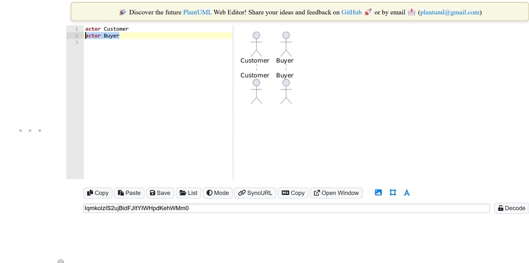
If someone purchases from an online store, write: actor Buyer
This shows the Buyer is a user of the system.
Use Cases:
Use cases show the tasks the system can handle from the user's point of view.
Syntax: usecase "Place Order"
Example:
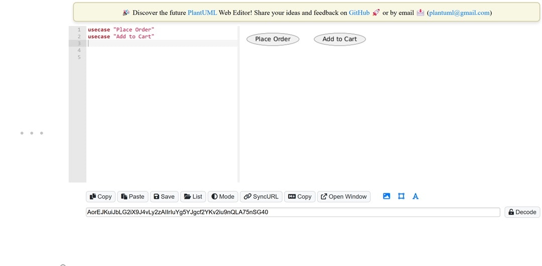
If you're writing for a shop: usecase "add to cart"
This depicts what you can do with a system.
Relationship:
Relationships connect actors and use cases or link one use case to another.
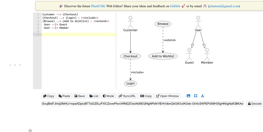
- Association: You can use it to link actors and use cases.
Syntax:
Customer --> (Checkout) - Include: it helps add shared behavior to a base use case:
Syntax:
(Checkout) ..> (Login) : <> - Extend: You can utilize it to represent optional or conditional actions:
Syntax:
(Browse) ..> (Add to Wishlist) : <> - Generalization: Use it to gather similar actors:
Syntax:
User --|> Guest
User --|> Member
Steps to Create a Use Case Diagram with PlantUML
Drawing a diagram with code is pretty straightforward once you know what elements to include. But before you start, it's important to have a plan. Who will use the system? What exactly will they do? How are the different parts connected? Let's go through each step together to help you build a clear PlantUML use case diagram example.
Step1Identify the Actors of the System
Let's start by listing everyone who interacts with the system. Think of them as people outside the main system, each with their specific role.
For example, in a food delivery app, the main actors are the customer, the restaurant staff, and the delivery rider.
An admin can also play a part in keeping everything running smoothly.
Step2Identify the Use Cases of the System Supports
Think about things from each actor's perspective. What do they need the system to do?
Write down their main tasks. For example, a customer places an order and tracks their food.
A restaurant manages incoming orders, a rider delivers the food, and an admin keeps an eye on everything.
Step3Define the Relationships Between Actors and Use Cases
Start by connecting each actor to what they do. This helps clarify who's responsible for each task.
For things that different actors share, like logging in, connect those to multiple actors. Use arrows to show the direction from the actor to the use case.
Only add, include, or extend if it helps explain things better.
Step4Write the PlantUML Code
Turn your ideas into straightforward diagrams with simple code. Just describe the actors and their actions using plain text.
Start with @startuml and finish with @enduml. Use arrows to show connections, and put names with spaces inside double quotes.
Keep your code neat and organized to make it easier to understand later on.
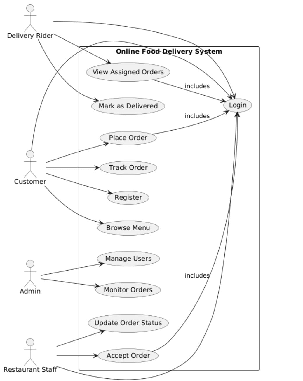
Code for PlantUML:
@startuml
left to right direction
skinparam packageStyle rectangle
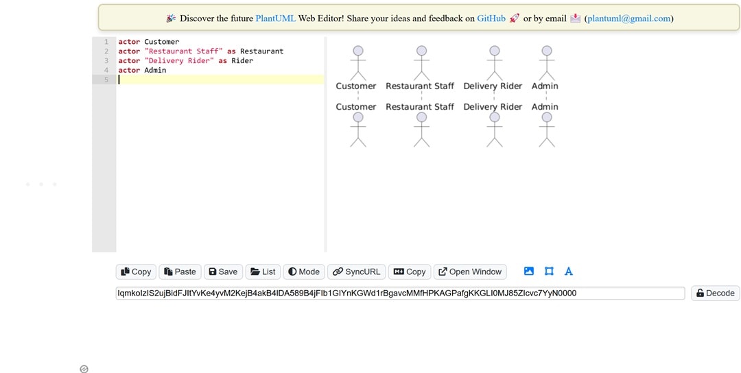
actor Customer
actor "Restaurant Staff" as Restaurant
actor "Delivery Rider" as Rider
actor Admin
rectangle "Online Food Delivery System" {
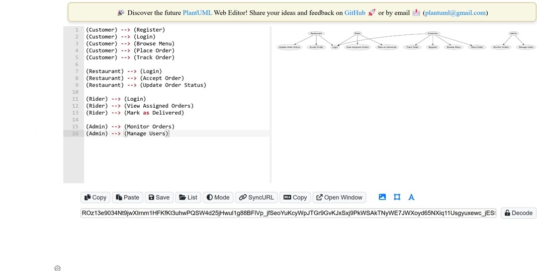
Customer --> (Register)
Customer --> (Login)
Customer --> (Browse Menu)
Customer --> (Place Order)
Customer --> (Track Order)
Restaurant --> (Login)
Restaurant --> (Accept Order)
Restaurant --> (Update Order Status)
Rider --> (Login)
Rider --> (View Assigned Orders)
Rider --> (Mark as Delivered)
Admin --> (Monitor Orders)
Admin --> (Manage Users)
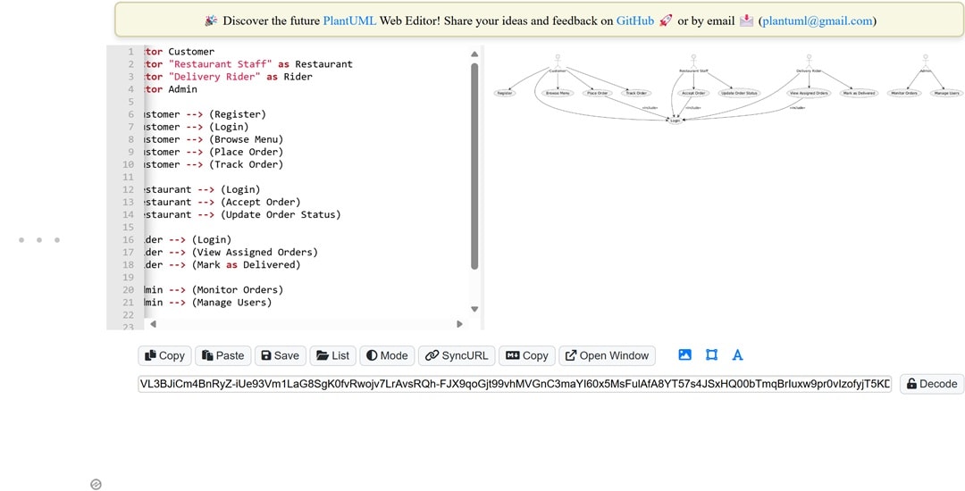
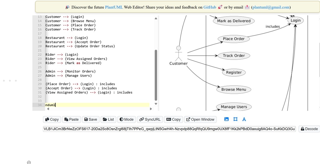
(Place Order) --> (Login) : includes
(Accept Order) --> (Login) : includes
(View Assigned Orders) --> (Login) : includes
}
@enduml
Step5Render the Diagram using a PlantUML Tool
Just paste your code into a PlantUML tool, and you'll see the diagram pop up instantly.
You can choose an online editor, use a plugin in your IDE, or go for a desktop app. Whatever feels easiest for you.
Once you run it, the diagram appears right away. No waiting, no complicated setup.
Practical Examples
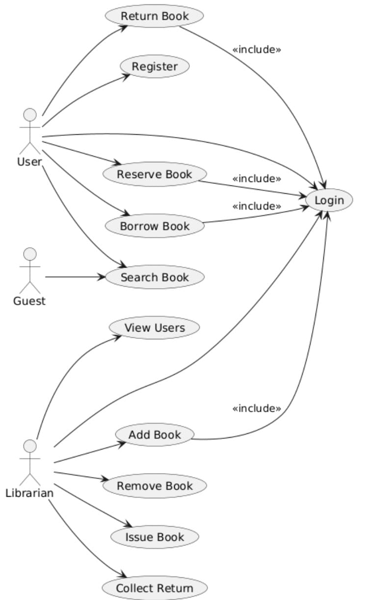
Now, we will be discussing a library management system example. We will also provide PlantUML syntax for use case diagrams.
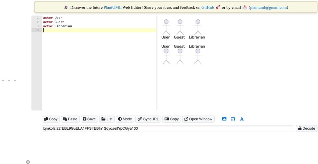
Example 1Pinpoint the Actors
- Instead of focusing on names, it's better to think about roles.
- A user is someone who borrows books, a guest can only search and browse, and a librarian handles all the management tasks.
- These are the main roles your system should recognize and respond to.
Example 2Use Cases For Library Management System
- A User borrows and returns books. A Guest can only search for books.
- A Librarian keeps everything running smoothly and updates the system.
- Focus on what they need to do, not how they do it.
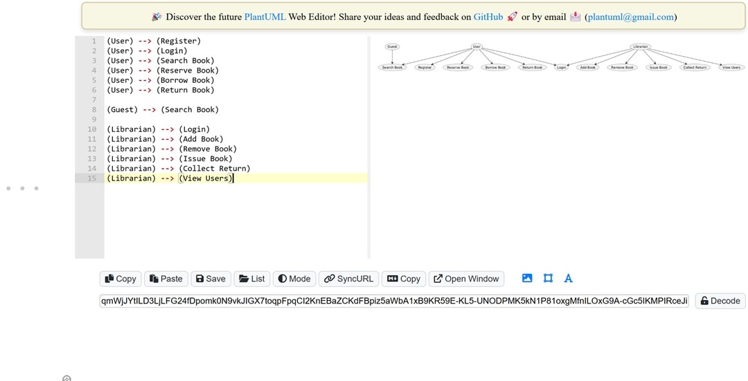
Example 3Links the Library Actors and Use Cases
- Connect each actor to their actions
- Show who does what. If two actors perform the same feature, link both of them.
- Use arrows to make everything clear.
Example 4Write the PlantUML Code
- Make sure to use clear actor names and specific labels for each use case.
- Keep the layout simple and consistent, always following the same direction.
- Aim for easy readability. If one step depends on another, include links to connect them.
- And don't forget to follow the structure. You want your diagram to look organized and clear.
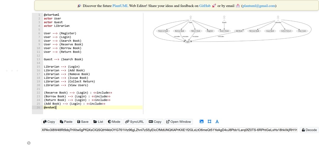
Code for PlantUML:
@startuml actor User actor Guest actor Librarian User --> (Register) User --> (Login) User --> (Search Book) User --> (Reserve Book) User --> (Borrow Book) User --> (Return Book) Guest --> (Search Book) Librarian --> (Login) Librarian --> (Add Book) Librarian --> (Remove Book) Librarian --> (Issue Book) Librarian --> (Collect Return) Librarian --> (View Users) (Reserve Book) --> (Login) : <> (Borrow Book) --> (Login) : < > (Return Book) --> (Login) : < > (Add Book) --> (Login) : < > @enduml
Example 5Generate Use Case Diagram
- Paste your code, and the tool will handle the rest.
- You'll see your actors and actions displayed in a clear, easy-to-understand diagram.
- If the labels overlap or everything feels too crowded, you can tweak the layout settings in your code to get it looking just right.
When to Consider Alternatives
PlantUML is a great tool for developers who are comfortable writing code. But not every team has the same skills or preferences. If typing out syntax feels like an obstacle or slows down your work, it might be worth exploring other options. Let's look at some of the limitations of PlantUML and a visual alternative that could work better for you.
PlantUML Limitations
PlantUML is a handy tool, but it's not perfect. Some people might find it a bit slow, confusing at times, or tricky to use if they're unfamiliar with coding.
- No Visual Editing: PlantUML doesn't have drag-and-drop features, so you'll need to write the code for every change. This can make quick edits a bit slower compared to tools with visual editing.
- Hard for New Users: If you're new to coding, getting the hang of the syntax can take some time. At first, even simple diagrams might seem a bit overwhelming or confusing.
- Manual Layout Adjustments: PlantUML doesn't always line up the elements perfectly. Sometimes, you'll need to tweak their positions a bit through trial and error to make everything look tidy.
Try a Simple GUI-Based Tool
Let's be honest— code allows for more control, but it may not always be efficient. It doesn't help when you have tight deadlines or people with no syntax experience. If your priority is fast performance or easy editing, then changing to a GUI-based option might save you hours. This is where EdrawMax comes into play.
EdrawMax makes it easy to work with UML diagrams by offering a built-in library of shapes like actors and use cases. You can label interactions visually within the same screen. Unlike PlantUML, you can group related elements and apply themes customized for use cases. This is all without messing around with syntax or manual layout adjustments.
Why You Will Love It
- Rich Templates: Explore several ready-to-use templates for different use cases, from business processes to IT systems.
- Intuitive drag-and-drop UI: Our drag-and-drop interface makes it easy to add actors, use cases, and connections with just a click. There's no need for coding or arranging everything manually.
- Flexible Exports: When you're finished, export your diagram in formats like PDF, PNG, SVG, Word, or Visio.
Final Words
Creating diagrams with simple code gives developers full control and makes it easy to keep everything in check. Whether you're identifying actors or mapping out relationships, each step stays organized. You've probably seen how to set roles and connect everything with arrows. The PlantUML Use Case Diagram is a great choice when you want something flexible and based on text.
Not everyone enjoys working with code. If syntax feels like a challenge, tools like EdrawMax Online could be a better fit. They let you avoid manual typing and instead offer drag-and-drop features. This makes diagramming quicker and easier without sacrificing clarity.
That said, if you need clear documentation, using a use case diagram with PlantUML code is still a reliable option, especially for tech teams. For non-technical folks or when you need fast mockups, visual tools like EdrawMax Online make creating diagrams more straightforward, all while keeping your structure intact. Give EdrawMax a shot today and see the difference!