


Our devices use LEDs to create light signals. These signals show if the devices are working properly. The low-power elements transform electricity into visible light which emits from each tiny enlightened source. These devices appear in multiple tools including small toys and big TVs.
A good circuit design requires knowledge of LED symbol representations. The guide illustrates the different LED symbols together with their operational functions. EdrawMax enables users to generate clear circuit plans by using these circuit components.
In this article
All Common Types of LED Symbols
Diode LED
An LED symbol resembles a diode containing two small arrows. The two arrows indicate that light exits from the device. Power enters through the flat line section of the symbol. Power exits from the point which is marked on the symbol.
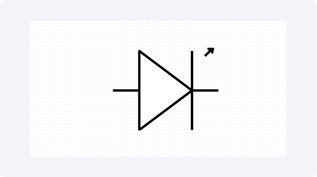
Most tools utilize this LED type for power lights as well as status signs and basic alert functions. The light rays originate from the direction indicated by the arrows. LEDs operate effectively on small cells because they consume minimal power therefore making them suitable for small tools.
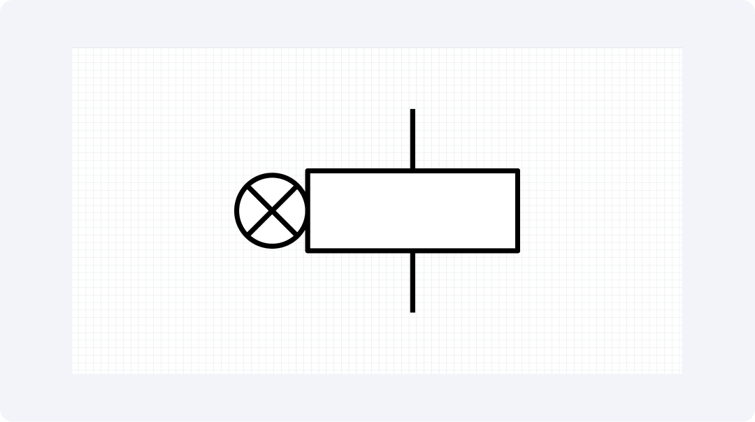
Surface Mount LED
The Surface Mount LED functions by directly connecting to electronic circuit boards. In the symbol, a flat pad area replaces the usual wire leads. The overall size requirements of small tools decrease when implemented with this design

Small LED dimensions make them suitable for building compact tools including mobile phones and wristwatches. The board surface stays unharmed when these LEDs connect to it because the attachment process leaves no holes. LEDs prove suitable for compact tools because of their structural design features.
Infrared LED
Similar to regular LEDs the Infrared LED operates identically but features an "IR" marking on it. The symbol contains dash lines that show this component produces light that humans cannot see.

The LEDs produce an invisible wavelength that powers TV clickers and alarm tools as well as data sharing devices. The symbol exists in specifications for TV clickers and both motion tools and light talk tools. The invisible light serves as an essential operational component that makes various devices work efficiently.
Alphanumeric LED
The Alphanumeric LED contains multiple light components which allow it to form numeric and word displays. The symbol presents a rectangular shape with internal components. The diagram demonstrates how to connect wires to create shape illumination.
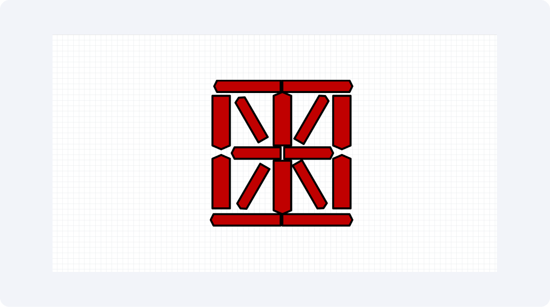
The symbol illustrates the correct wiring method for all connection points. Most devices need seven components to form shapes yet additional elements enable users to create multiple shapes. It is mostly used in digital clock circuits or digital logic circuits.
LED Coil
The LED Coil contains a series of many LEDs which appear either linear or curved. The symbol displays connected LED marks which are represented through lines between them. LED strips intended for lighting purposes carry the designation LED Coil.
LED coils use their illumination power to illuminate houses and cars as well as stores. The symbol can be found in residential light design drawings. Multiple light points receive power from a single electrical connection according to the links in the diagram.
RGB LED
An RGB LED contains red, green, and blue LED components within a single casing unit. A single link joins three LED parts each with their independent inputs according to the symbol. This means it can mix shades.

These components generate complete color effects within new devices. The symbol appears in music tool designs and gaming tool designs as well as smart home products. Using power control settings allows RGB LEDs to produce various colors from a single element.
Explore More NOT Gate Symbols on EdrawMax
The circuit diagram collection of EdrawMax includes numerous symbols for representing LED elements. The tool kit includes 26,000 easy-to-use shapes for its users. EdrawMax provides all the required elements for either small lighting designs or large-scale LED display creation.
The application EdrawMax assists users in creating high-quality plans across multiple needs. Both new users and pros like the app. It offers advanced features and a simple interface. The software provides functionality for both brief sketches and complete plans which serve every drawing requirement.
- Key points that make EdrawMax great for LED work:
- Has more than 26,000 parts for full plan needs.
- Use drag and drop so you can make plans fast.
- Gives you start maps to help new work begin.
- Works on all main desk apps like Mac and PC.
- Saves work as PDF, PNG, and more types.
How to Find More Symbols on EdrawMax?
Step 1Launch EdrawMax
Open the EdrawMax application and log in to get started.

Step 2Create a New Project
Click on the "New" tab in the interface. Then, choose "Blank Diagram" to start a new workspace for your project.

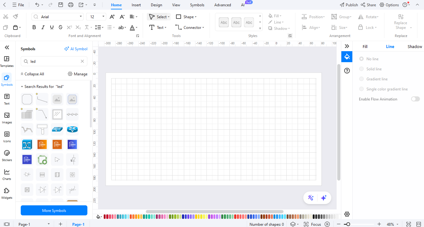
Step 3Access the Symbol Library
Use the left menu to access Symbols in your workspace. Navigate to the Symbols panel to find symbols available from EdrawMax. Each diagram style exhibits its unique format within the symbol collection.
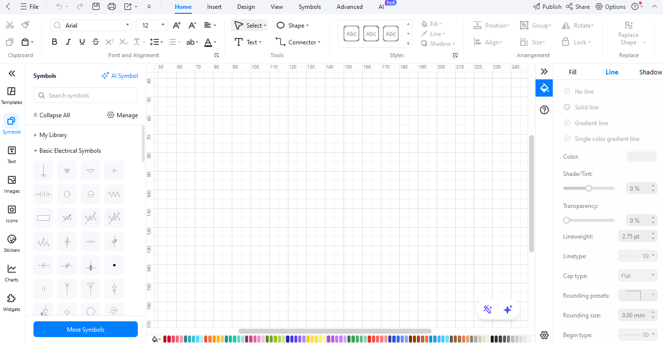
Step 4Search for Specific Symbols
The search bar at the top of the page enables users to find symbols by entering their desired terms.
Step 5Download Additional Symbols
Click on "More Symbols” at the bottom of the symbol library to find downloadable symbol packs in the pop-up window options. Select the symbol packs you desire from the available collection.

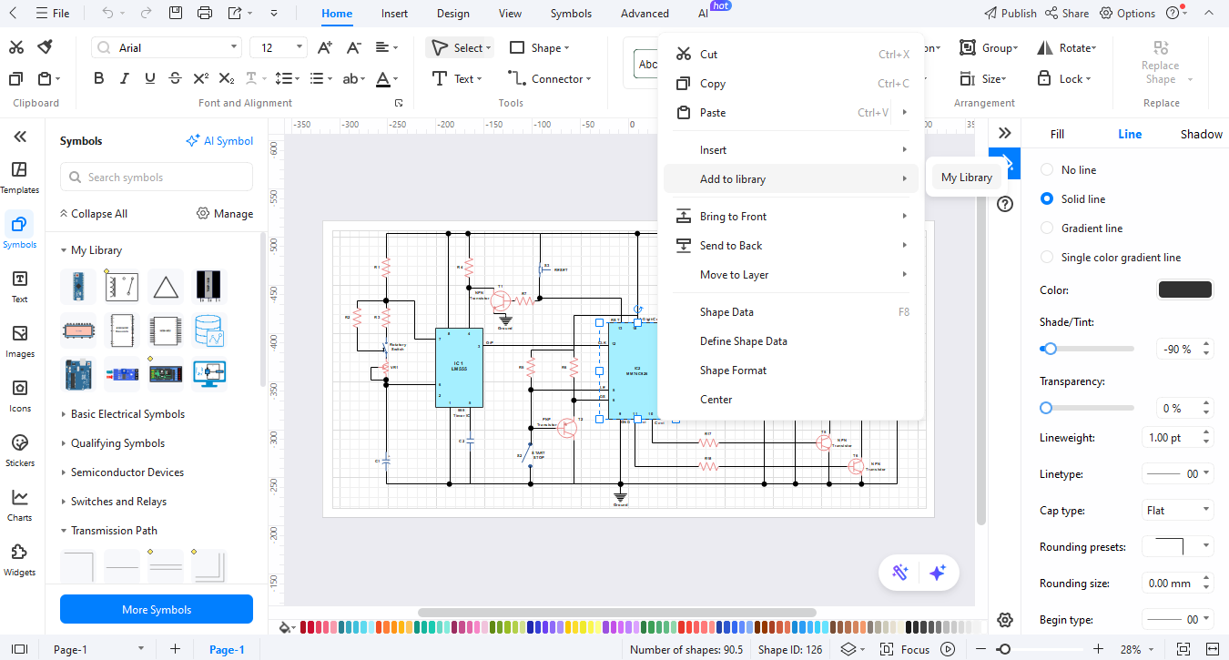
Step 6Create Custom Symbols
In EdrawMax, users can create custom symbols using its building system. To do this, right-click on a new symbol. You can save your new asset to recent diagrams by selecting "Add to Library" from the right-click menu.
How to Make a Circuit Diagram on EdrawMax?
The software EdrawMax helps users create circuit diagrams with ease. Whether you’re starting from scratch or using a template, here’s how to do it step by step:
Step 1Open EdrawMax
Launch and log in to EdrawMax, then select "New" under the main menu options.

Step 2Select a Template or Start from Scratch
Select an electrical diagram. Choose "blank drawing" to start from scratch. Or, use "new from templates" for built-in templates.

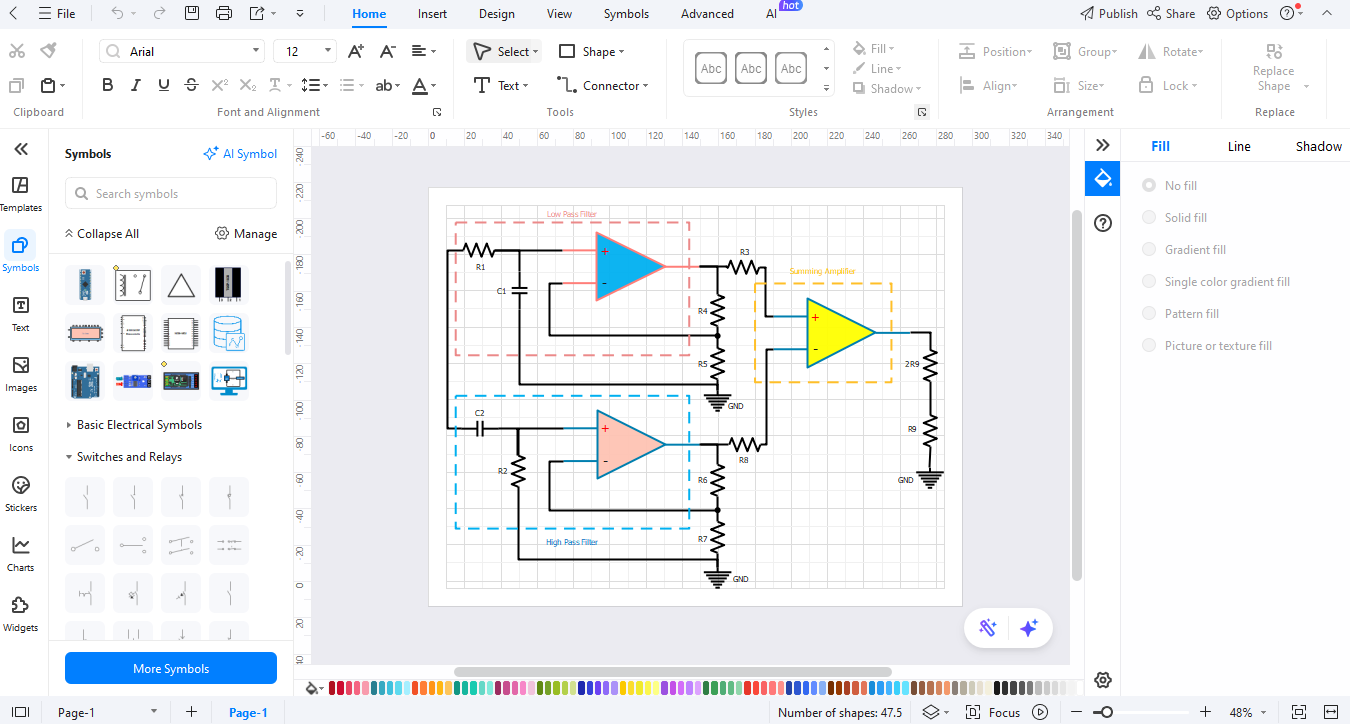
Step 3Add Circuit Symbols
Open the symbol library. Place the required capacitor symbols with the other elements on the workspace to create your schematic. To link your elements, use drawing tools to place wires or lines. The smart connectors in EdrawMax help users align and wire components.
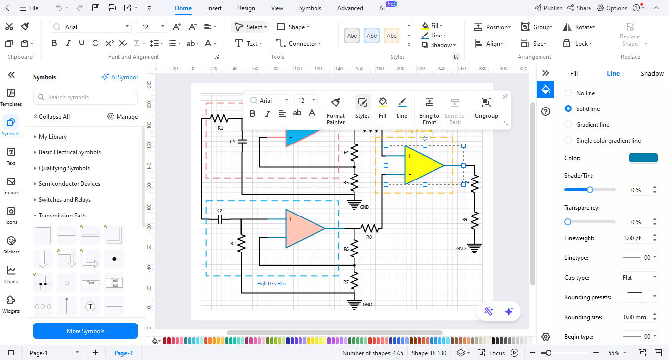
Step 4Arrange and Customize
Your design needs labels and either text annotations or dimensions for clarity. You can apply formatting options from the toolset to improve the way your diagram looks.
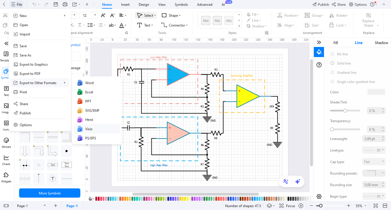
Step 5Review and Export
After finishing your diagram, review it and select "Export" to generate and save it in the desired format like PDF, PNG, or Visio files for sharing and printing purposes.
Ending Notes
LED diagram symbols are useful for designers and school admin teams to see how systems work. The symbols help people understand complex concepts more easily. New designers and professional experts can use EdrawMax to create effective LED circuits that effectively present their concepts.
EdrawMax demonstrates how simple it is to create electrical designs. Using this tool enables users to display their LED plan ideas effectively due to the intuitive design elements and clear visual interface.
AI Diagram Generator
Enter your prompt. Upload files if needed. Generate diagrams, charts, or slides instantly.


