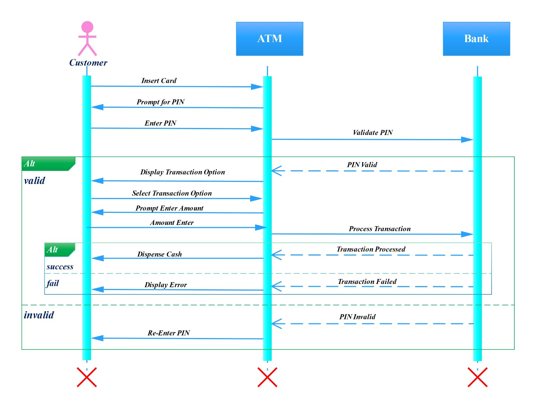
About this Sequence Diagram for ATM template
This template outlines the step-by-step logic of an automated teller machine. It covers authentication, transaction processing, and error handling. Developers use this to visualize system behavior and ensure all financial protocols are met during the coding phase.
Authentication Phase
The process begins when a customer inserts their card into the machine. The ATM then prompts for a PIN to verify the user identity. This stage is crucial for maintaining security and preventing unauthorized account access.
- Insert Card
- Prompt for PIN
- Enter PIN
- Validate PIN with Bank
Transaction Selection and Processing
Once the bank validates the PIN, the system displays available options like withdrawals. The customer selects a service and enters the desired amount. The ATM then sends a request to the bank to process the transaction.
- Display Transaction Options
- Select Transaction Option
- Prompt Enter Amount
- Process Transaction
Outcome and Error Management
The diagram includes alternative paths for successful and failed actions. If funds are available, the machine dispenses cash. If a PIN is wrong or funds are low, the system displays an error message or asks for a retry.
- Dispense Cash on success
- Display Error on failure
- Transaction Processed confirmation
- Re-Enter PIN for invalid inputs
FAQs about this Template
-
What is the primary purpose of an ATM sequence diagram?
An ATM sequence diagram serves as a visual blueprint for the interactions between a user and the banking system. It identifies every message exchange, from card insertion to cash dispensing. By mapping these steps, software engineers can find potential logic flaws or security gaps early. This ensures the final banking software operates reliably and handles various user inputs safely.
-
How do alternative frames work in this diagram?
Alternative frames, labeled as Alt, represent conditional logic within the system. In this diagram, they show what happens based on specific triggers like a valid or invalid PIN. One path leads to a successful transaction, while the other handles errors or retries. These frames allow developers to see multiple possible outcomes within a single, organized visual representation.
-
Which actors are involved in an ATM sequence?
There are typically three main actors or objects in this sequence. First is the Customer, who initiates the process. Second is the ATM itself, which acts as the interface. Third is the Bank server, which manages the database and authorizes funds. Together, these three lifelines demonstrate the end-to-end flow of data and physical actions during a bank visit.

 (AI & Web)