


Microcontroller 8051 is a basic microcontroller designed for embedded systems technology. Intel developed this controller in the 1980s. It came with a Harvard architecture. NMOS technology was used to develop it. This technology operates at more power. Therefore, it was redesigned with CMOS technology. The letter C was introduced in the later versions. For example, 8051 is an 8-bit controller.
The updated versions of this microcontroller operate at a lower power than the older versions. This controller has two memory spaces of 64Kx8 size and two buses for data units and programs. Moreover, it has 8-bit accumulator units and an 8-bit processing unit. Read more to understand the complete architecture of this controller.
In this article
Part 1. What Is a Block Diagram of 8051 Microcontroller
The b8051 microcontroller block diagram expresses the internal functioning of logical operations and memory segmentation.
This diagram helps engineers, students, and hobbyists understand how the microcontroller functions and how its various components interact.

Key Components of an 8051 microcontroller block diagram
All components are built in a single chip. Below is a list of the components of the 8051 controller. Let’s have a look.
1. Central Processing Unit (CPU)
This component controls every single operation of the controller, which is why it is commonly called the brain of the controller. The in-built elements of the central processing unit are as follows:
- ALU: It is a short form of Arithmetic Logic Unit. This element performs all mathematical operations, like division, multiplication, subtraction, and addition. In addition, it can also perform logical operations, including NAND, NOT, AND, XOR, and OR.
- Program Counter: A 16-bit data address is stored in the program counter. It also keeps track of the program sequence.
- Stack Pointer: It is a variable element that stores another variable’s address. It can store addresses of up to 8-bit where the data was stored last time.
- Accumulator: This is an 8-bit register. It performs the automatic storage action of all mathematical operations within the controller.
- Registers: These are commonly known as the storing units. The registers that are mainly used in the 8051 microcontroller are general-purpose registers. This controller consists of 34 general-purpose registers in total. Two of all the registers - A and B - deal with the mathematical core of the controller, whereas the other 32 registers are part of the internal RAM.
- Timing and Control: It performs internal operations with data flow control and clock signal frequency of the 8051 microcontroller.
2. Oscillator Circuit
This component of the 8051 microcontroller generates clock pulses to perform the operations of the controller. Therefore, it is also called a clock generator. The oscillator circuit comes with a frequency resonator and various electrical components. The frequency resonator decides the frequency of the clock pulse and the functioning speed.
3. ROM & RAM
Like all microcontrollers, the 8051 has certain memory to store programming code and data. This memory is often called a memory chip. Generally, memory is divided into two types: RAM and ROM, as discussed below.
- RAM: It is a short form of Random Access Memory. It is responsible for storing data, which is why it is named as chip data memory.
- ROM: The word “ROM” stands for Read Only Memory. Its primary responsibility is to store the program instructions. ROM can read the program when a controller is operating or performing its functions.
4. Timers & Counters
Two 16-bit (or 2-byte) timers and counters are equipped with an 8051 microcontroller. The counters are further divided into an 8-bit register. They are used in calculating the number of events, like pulse counting, frequency measurements, pulse width measurement, and more. In addition, timers and counters are also used to determine the time period.
5. Interrupt Logic Circuitry
This logic circuit sense interrupts in an 8051 microcontroller. It consists of interrupt priority registers, interrupt enable registers, and several other elements.
6. Serial & Parallel I/O Ports
The 8051 controller has 4 I/O ports to connect with external devices. Since a controller is used to control different machine operations, I/O ports are required to transfer the data.
Part 2. What Is a Pin Diagram
There are 40 pins in total for the 8051 microcontroller. We can use a pin diagram, a visual representation of the pins on an integrated circuit (IC) or microcontroller, to see their connections and functions.
Some of them perform separate individual functions, whereas others are used in groups to perform a certain task within the controller. Let’s get into further specifics.

| Pin | Function |
|---|---|
| 1 to 8 | These pins combine to make Port 1. This is a bi-directional I/O port. |
| 9 | This pin sets the controller to the primary value; therefore, it is known as a Reset pin. |
| 10 to 17 | Port 3 is formed with these eight pins. This port is used for various functions, like interrupts, timer input, and serial communication indicators for transfer and receival of the data. Port 3 is also known as a domestic pull-up port. |
| 18 and 19 | These two pins are used to interface the given system clock with the outer crystal oscillator. |
| 20 | It is denoted as Vss. This pin symbolizes 0V or ground voltage of the 8051 controller. |
| 21 to 28 | Port 2 is formed with these eight pins. This port is used as an I/O port. It multiplexes the senior order address bus. |
| 29 | It is PSEN or a Program Store Enable. You can interpret the sign from the outer program memory with this pin of the controller. |
| 30 | It belongs to EA or External Access. It is used to prohibit or permit the interfacing of the outer memory. This pin is linked to the supply voltage to set it to high. |
| 31 | It belongs to ALE or Address Latch Enable. It is used to demultiplex the Port 0 address data indication for interfacing with the outer memory. |
| 32 to 39 | These eight pins combine to form Port 0 of the controller. This is a bi-directional I/O port that multiplexes data bus signals and lower-order addresses. To utilize this port, you need outer connected pull-up resistors. |
| 40 | With this pin, you can provide your circuit with the power supply. |
Part 3. Key Features of 8051 Microcontroller
Potential features that make this controller stand out in the market are as follows:
- The data memory is 128 bytes on-chip RAM.
- The program memory is 4096 bytes on-chip ROM.
- This controller has a 32-bit input/output line that is arranged as four 8-bit units.
- It has 16-bit timers and counters.
- The intrusion cycle of the 8051 microcontroller is only one microsecond. It is because of the 12MHz crystal.
- It carries 12 user-defined flags.
- Four register banks of 8 bits each are available within the controller. It has a direct bit and byte addressability.
- It has a two-level prioritized interrupt structure.
- This controller consists of parity computing features, a high-speed programmable serial port, and multiple modes.
- It has three internal and two external interrupts.
- A 16-bit unidirectional address bus.
- An 8-bit bidirectional data bus.
Part 4: How to Make an 8051 Microcontroller Block Diagram
An 8051 Microcontroller block diagram is used to understand the basic concepts and working of the microcontroller. It is easy to make such a block diagram if you are using the right tools.
Here, we will use EdrawMax, a professional block diagram tool. It's also an all-in-one diagram drawing tool that provides so many features:
- Templates Library: EdrawMax provides a large library of templates for your designs. You can find multiple diagram types in the library.
- Easy to Use: EdrawMax has a user-friendly interface and a bunch of hotkeys. Also, there's this quick guide to help you make a diagram quickly.
- Drag-and-Drop: EdrawMax has drag-and-drop functionality, making the work even easier. You can add images and designs whenever needed.
Now, let's check out how to create a block diagram for the 8501 microcontroller.
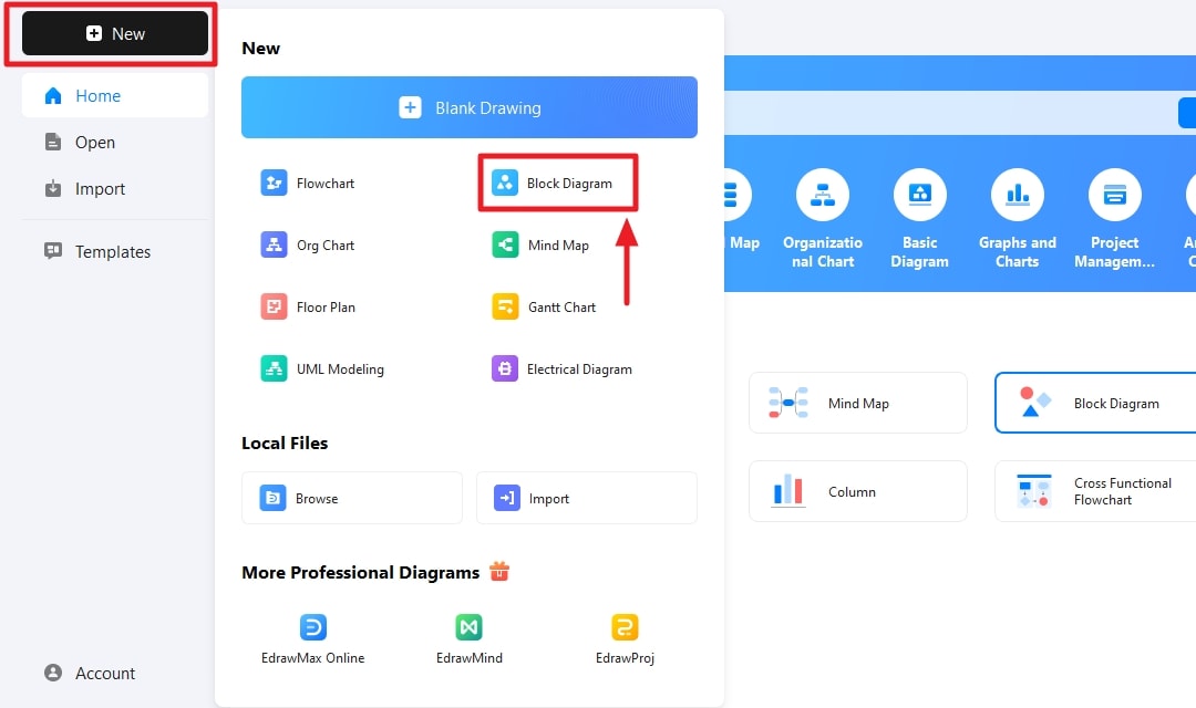
Step 1: Open New and Find Block Diagram
Open EdrawMax and click “New” and find “Block Diagram” from the given options.
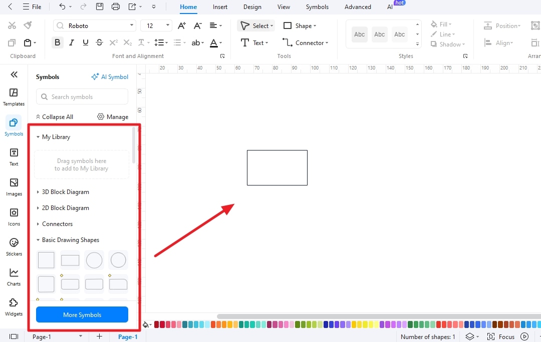
Step 2: Drag needed elements
Drag all the elements needed to complete your block diagram.
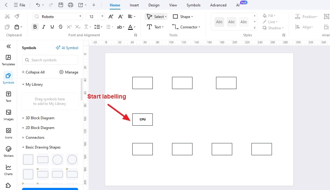
Step 3: Arrange the elements and start labelling them
Arrange the elements and label each element to bring clarity in the diagram.
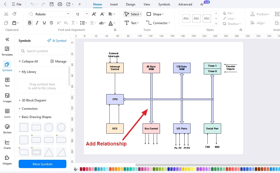
Step 4: Draw Relationships among the elements
Add relationships among all the elements and change the colors of the diagram to make your design look better.
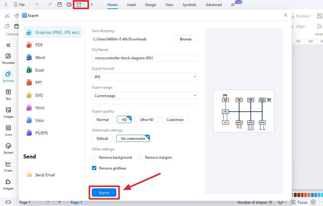
Step 5: Export your file
Export the file in your needed format and don’t forget to save the source file for further editing.
Part 5. 8051 Microcontroller Applications
This controller offers a wide range of applications in different areas. Three of the most common areas where the 8051 microcontroller is used are as follows:
1. Measurement Applications
This area includes using the 8051 microcontroller for current meter objects, voltmeter applications, handheld metering systems, and measuring and revolving objects.
2. Daily Life Applications
It covers the use of the controller in automobile applications, temperature sensing and controlling devices, defense applications, fire detection and safety devices, and light sensing tools.
3. Industrial Applications
This controller is used in process control devices and instrumentation devices at the industrial level.
Other applications of this controller include energy management, touch screens, medical devices, robotics, remote sensing, home appliances, consumer applications, and the list goes on.
Ending Note
The 8051 microcontroller - a single-chip computer system - uses a single integrated circuit to combine the functionalities of memory, microprocessor, and different peripheral devices. With this integration, the controller provides an effective solution for managing and controlling various electronic systems. You can understand the complete architecture of the 8051 microcontroller with its block diagram.
The block diagram shows all the components, including but not limited to CPU, memory, bus control, interrupts control, timers, and counters. In the above discussion, the block diagram of the 8051 microcontroller is presented, along with a brief description of all components and elements to understand the architecture in a better way.
Moreover, the pin diagram of this controller is also part of the discussion above. It shows how different pins are divided into different categories. Some are used individually, whereas others combine to form a single port. Real-life applications and features of the controller are also presented above.
AI Diagram Generator
Enter your prompt. Upload files if needed. Generate diagrams, charts, or slides instantly.


