An object diagram in UML is a visual representation of class instances and their relationships at a particular time. Object diagrams are depicted using intuitive notations to show a system screenshot. Some object diagram notations are aggregation, dependencies, composition, link, association, and object box.
While an object diagram helps examine a specific system iteration, it also generates a high-level overview. Some object diagrams used in programming languages include Swift and Java object diagrams. While you discover how to create an object diagram in Visio, you start by having a basic understanding of object diagrams across various applications and professions.
In this article
Part 1: How to Create an Object Diagram in Visio?
A UML state diagram (also known as a state transition diagram) denotes how an object responds to an event or outside stimuli, depending on which state the object is. In Visio, a state machine diagram can be created to depict the behavior of a specific part of a system. The object can be a computer program or a device. Here is the step-by-step process to create a state machine diagram in Visio:
Step 1:
Launch the desktop version of MS Visio on your system. Open a new file and type UML State Machine in the search box. Select the diagram template, and a dialogue box will appear. Select the metric or US units option in the dialogue box and click "Create."
Step 2:
You will see the shapes window next to the diagram. If you don't find it, you can go to view→ task panes and select shapes. Another way is to click on expand the shapes window. Go to the view tab and select the check box next to the "connection point" option. The connection points will appear once you start connecting shapes.
Step 3:
Go to the shapes window and drag the shapes you want to include in your state machine diagram. To add text, click anywhere on the free space inside the shape. Use formatting options such as color, size, and font to customize the shape.
Step 4:
You must choose a set of shapes and colors for every different state to ensure uniformity. You can use the same type of shapes for similar shapes-for example, squares for normal states and triangles for final states. Select an appropriate color scheme that can show a clear differentiation between states and transitions. For example, you can use blue for normal states and yellow for transitions.
Step 5:
Next, give each state a descriptive name. Transition labeling should be concise and meaningful, depicting the action or event triggering the transition. You can add extra information, such as event conditions, to provide clarity.
Step 6:
To add layers to your diagram, go to the "view" tab, click on "task panes," and select "layer properties." To enhance the organization of your diagram, you can assign shapes and transitions to different layers. Use different colors to differentiate the layers and label each layer appropriately.
Although Visio is one of the ideal tools for creating state machine diagrams, some common pitfalls can hinder the diagram's efficiency:
- If your diagram does not clearly define states and transitions, they will look ambiguous and complex to understand. Descriptive labels should be used to avoid any confusion about their purpose and connection.
- The next challenge is overcrowding the diagram by placing too many states in one diagram. Here, again, layers can be used to categorize states and transitions. Keep enough white spaces to prevent diagram overcrowding.
- Without layers in the diagram, editing individual components could be cumbersome. Compared to other alternatives, the design elements could be more intuitive.
- On the pricing side, Visio can be expensive for individuals and business owners. The web version has limited features, so one might have to go for licensing to unlock advanced features for creating state transition diagrams.
Part 2: EdrawMax: Free Alternative to Visio for Creating an Object Diagram
Wondershare EdrawMax is a versatile tool for creating smart, creative, and simple diagrams for every idea you have or visualize. You can access the tool online and offline on Mac, web, Windows, Linux, and mobile. Due to its user-friendly interface, EdrawMax makes diagramming easy for everyone. It is an excellent alternative to Visio, simplifies the creation of flowcharts, UML diagrams, etc., and helps you easily modify VSDX and VSD files.
Features
- Customization and Auto-Layout: Achieve effortless alignment and distribution of elements with just one click. The Guide Line tool helps you organize objects easily. There is an intelligent layout feature that can change the shape by just moving your mouse.
- Hyperlink: To explain your work more precisely, you can embed hyperlinks in your diagrams.
- User-friendly Interface: The most prominent consideration for users is the interface. Due to the quality of its interface, EdrawMax is suitable for both beginners and professionals. Its intuitive interface ensures a smooth diagram-making process for beginners.
- Edraw AI: With EdrawMax AI, you can create over 20 types of diagrams, generate content, and text with ease. You can also draft business proposals and write programming code using AI technology. The various types include AI flowcharts, AI mind maps, AI tables, AI pie charts, AI funnel charts, and more.
- Template Community: Over 23000 free and editable templates are available, which can help you discover and learn about your next project. These template collections display a smooth business process and help you make better decisions.
Step-by-Step Guide to Make UML Object Diagram
Some examples of an object diagram include a company's structure or even a university course department. This shows how the objects behave with each other in a given period. EdrawMax has substantial templates and professional symbols, and one can follow these steps to make an object diagram on EdrawMax:
Step 1:
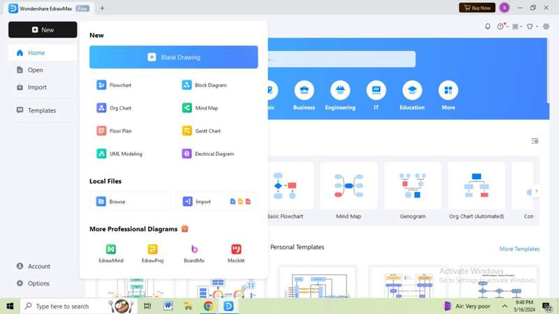
You can use the web or desktop versions of EdrawMax to create an object diagram. Launch and install the application on your system and go to the homepage. You have two options: select a pre-built template or create a new file.
Step 2:
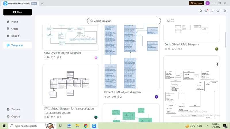
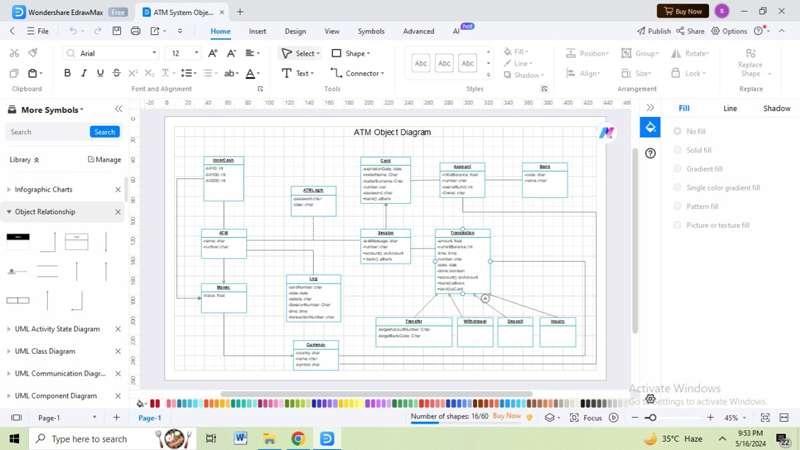
Click the "templates" option on the home page and type "object diagram" in the search bar. Scroll down and select your preferred template. Once you select the template, a new tab will open with the diagram on the canvas.
Step 3:
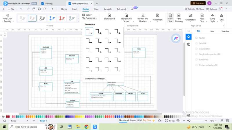
In the ribbon bar, you will find the "design" option where you can customize the diagram. You can change connector lines, color, text on the object, units, jump style, and more. If you want to customize a specific element, click on the component, and a floating toolbar will appear. From there, you can change fonts and styles and replace the shapes.
Step 4:
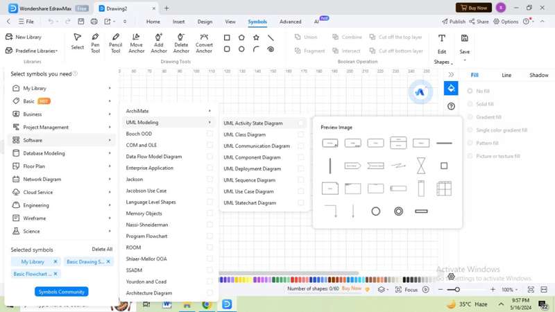
To create an object diagram from scratch, click "new" on the homepage. Click the "more symbols" option on the left navigation panel on the new page. In the drop-down menu, go to software→ UML modeling and check all the diagrams containing components for object diagrams.
Step 5:
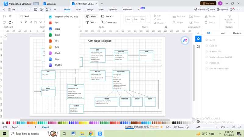
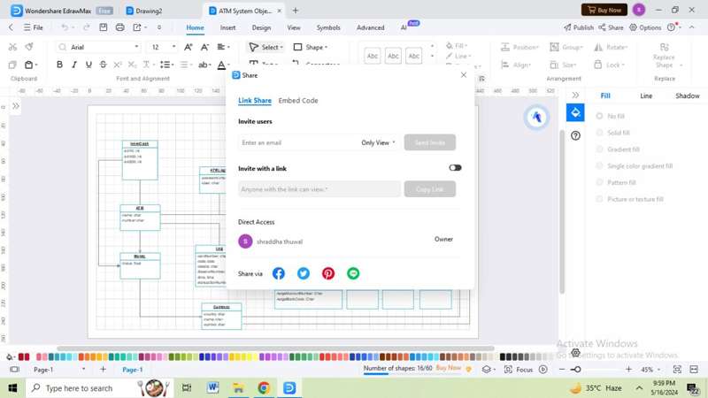
After customizing your diagram, save the file and click the "export" option on the ribbon. You can export your file in PDF, Excel, Word, SVG, Graphics, Visio, HTML, PPt, etc. You can also share your file or invite your team members by clicking the "share" option in the top right corner.
Step 6:
To publish your diagram in the template community, click the "publish" option at the top right of the ribbon. In the template community, you can find more than 23000 templates from fellow Edrawers and discover a new design. You can also share your design on social media or link it to your website.
Beginners can use EdrawMax to create object diagrams in forward and reverse engineering. During execution time, programmers can understand object behavior from a practical perspective.
Part 3: Object Diagram in EdrawMax
UML object diagrams denote an object-oriented programming approach to offer a more specific and concrete view. These are used as a subset of elements in a class diagram, reflecting diversity and roles. A Visio object diagram helps get a high-level system overview for a developer.
Learning how to create an object diagram in Visio is accessible and helpful. However, with advanced diagramming tools like EdrawMax, you get additional features that MS Visio may lack. EdrawMax is a superior alternative to Visio due to its multi-platform support, file compatibility, thousands of free symbols, affordability, and more.


