


Architectural drawings illustrate various building elements, including interior layouts, exterior views, elevations, electrical systems, and HVAC plans. One term you may encounter is “Beam Plan.” A beam plan is a detailed technical drawing that specifies the number of beams in a structure and the types of steel bars used for reinforcement. It’s a key tool on construction sites to ensure structural stability and safety.
Wondering how to create a beam plan? In this guide, we’ll explore the steps to draw and interpret one. Let’s get started.
In this article
What Is a Beam Plan?
A beam plan is a precise, technical drawing that presents key structural design details. It highlights the arrangement of steel reinforcement bars, stirrup hooks, beam dimensions, and load-bearing capacities.
The plan also incorporates related elements like shear walls and architectural features, including rooms, columns, and windows. This layout helps builders see how beams contribute to the structure’s strength and stability.
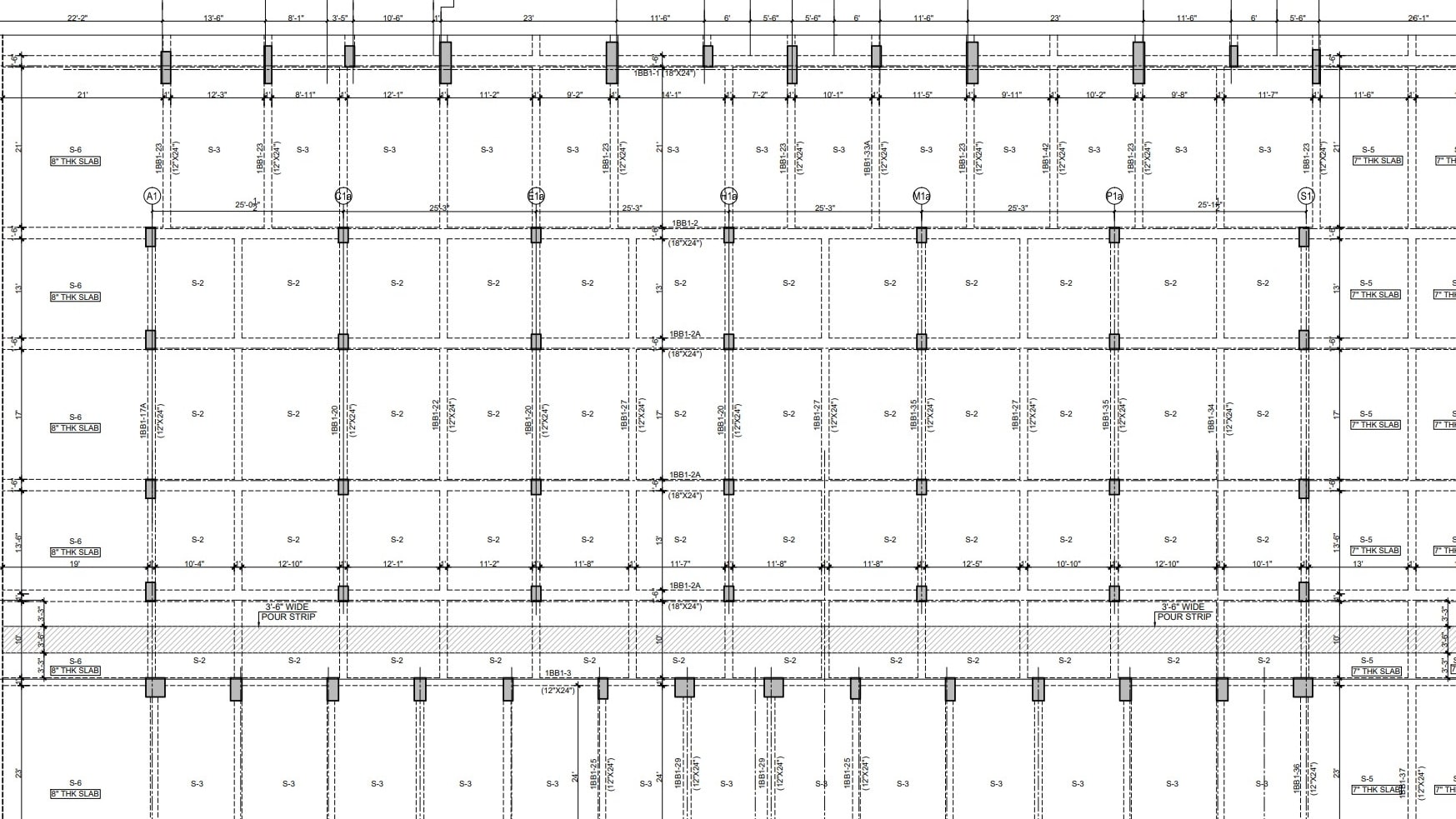
A beam plan is essential for equipping engineers and architects with critical structural details, enhancing construction efficiency. This architectural drawing varies in type, tailored to the specific layout and structure of the project.
Role of Beams in Structures
Beams are critical structural components that bolster a building’s strength by distributing loads effectively. Their size and placement directly influence their load-bearing capacity, making careful selection vital for resisting forces like earthquake shocks. As beam plans are key to construction, understanding their details is essential for success.
Types of Beam Plans
Foundation Beam Plan
A foundation plan is a detailed architectural drawing that outlines the dimensions and layout of a building’s foundation. The foundation beam plan specifies the placement of beams—such as grade, plinth, and tie beams, to ensure strong support for the structure above. This type is commonly used in high-rise buildings to enhance stability.
Floor Beam Plan
A floor plan is a top-view architectural diagram displaying a building’s components. The floor beam plan details the arrangement of primary beams, secondary beams, and joists to support the structure. It’s widely applied in multi-story buildings, commercial complexes, and industrial projects for effective load distribution.
Hut Beam Plan
This technical drawing illustrates a structure’s truss system from above, highlighting the assembly of rafters and tie beams. It clarifies how these elements work together to provide stability and support, often used in simpler or traditional structures like huts.
How to Read a Beam Plan? Symbols, Terminologies, and Legends
Understanding beam plans is crucial for ensuring construction efficiency, structural integrity, and safety. Reading these plans demands specialized knowledge of their symbols, terminologies, and legends. Misinterpreting a beam plan can result in serious structural issues or safety risks, making accuracy essential.
As an engineer, focus on beam placement specific to each plan type: foundation beams in a foundation plan, floor beams in a floor plan, and roof beams in a truss plan. Recognizing these distinctions helps prevent errors during construction. Architects use various symbols in beam plans, which may differ across drawings. Below are common symbols and terms to guide interpretation:
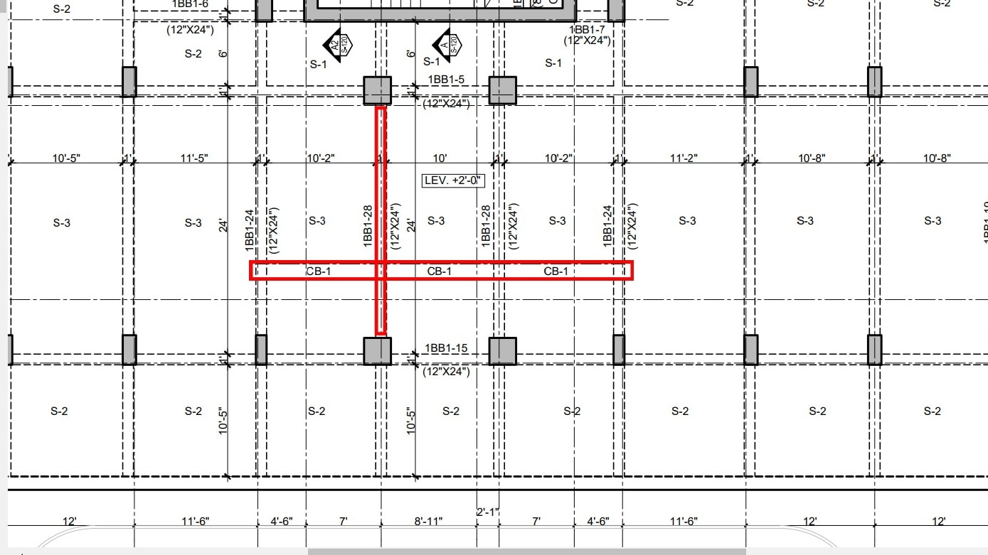
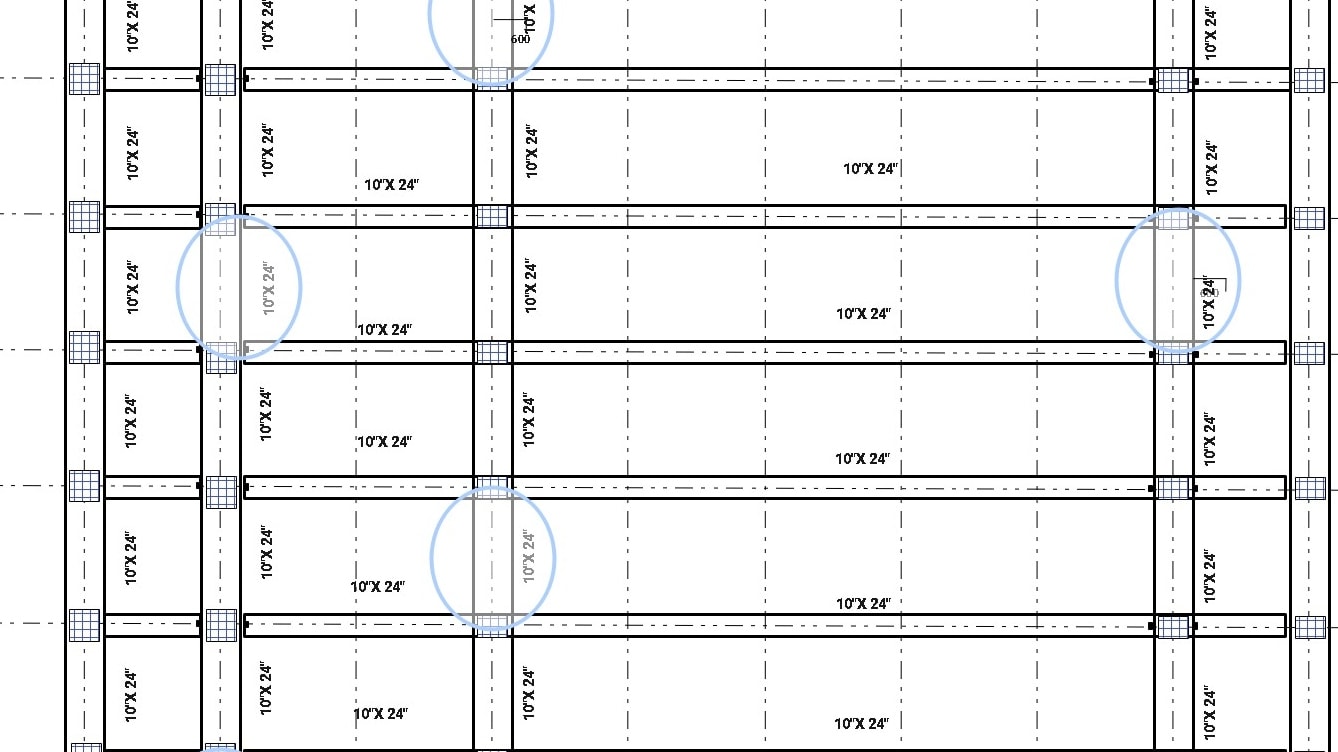
- B: This symbol represents a beam in the drawing.
- CB: This symbol represents a continuous beam in a drawing.
- S: This symbol represents a slab in a floor plan connected with columns.
- P: This symbol represents studs.
Beam plans are more complex than basic floor plans, using specialized symbols to improve comprehension. Component dimensions are shown within shapes, typically in a Width × Height format. For example, a beam might be labeled as 12” wide and 24” deep, as seen in some drawings.
Before creating a beam plan, architects, project managers, technicians, and engineers meet to finalize symbols and technical details. Here’s how to read one effectively:
- As an engineer or site supervisor, locate primary and secondary beams to confirm proper load distribution.
- Verify bar dimensions—width, height, and reinforcement specifics.
- Review each beam section carefully, ensuring alignment with architectural and structural standards.
Mastering beam plans boosts construction accuracy and prevents structural failures.
How to Draw a Beam Plan
In this section, we will guide you through drawing a beam plan for any building. We’ll also help you understand how to draw it using the easy and fast traditional wooden post-and-beam construction method.
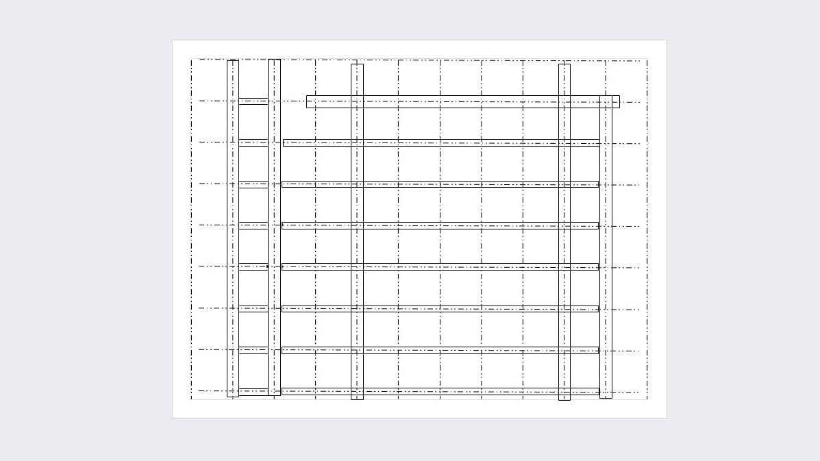
Draw Reference Lines

The first step when drawing a beam plan is to set up the reference lines. These reference lines identify the beams, the important structural component of a building.
Generally, the wood structures are shown by drawing vertical and horizontal dotted lines with a spacing of 910mm.
Add Beams in the Reference Lines
The next step is to add the beams using the reference lines. Make sure to add them after reading the proper dimensions the engineer or project manager provides. In addition, note down the dimensions of the floor joist.
Add Columns
Add columns around the beam layout after adding the beams and other necessary details. These columns are traditionally drawn when a primary or secondary beam meets to transfer the load efficiently.
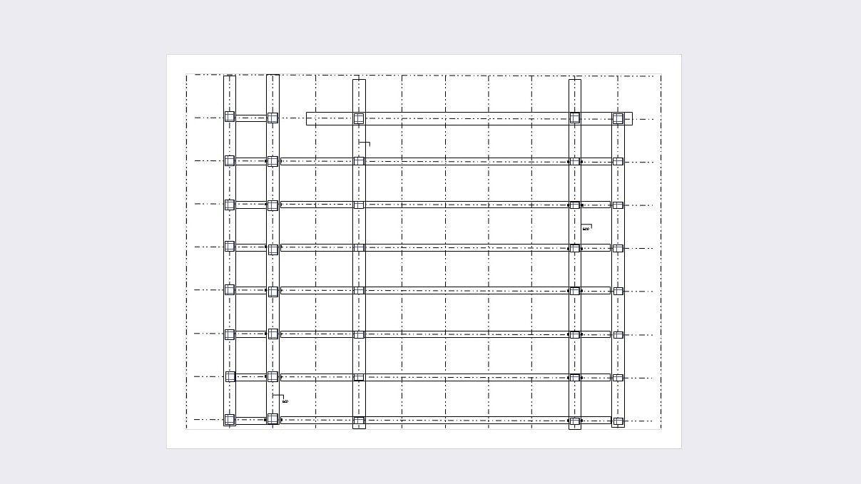
If pillars need to be installed in areas without existing floor beams, additional floor beams must be added and adequately integrated to provide structural support.
Add Joist Position and Dimensions for Beams
The floor beams are installed when we join them together. Therefore, we must add the joist position and metal fittings area.
It's better to pay attention when adding dimensions and joist positions because most mistakes occur during this process.
These positions and dimensions depend on the type of structure and vary in different situations. Ensure all necessary information is reviewed and included before creating the drawing, and proceed with drafting.
Recommended Drawing Tool: EdrawMax
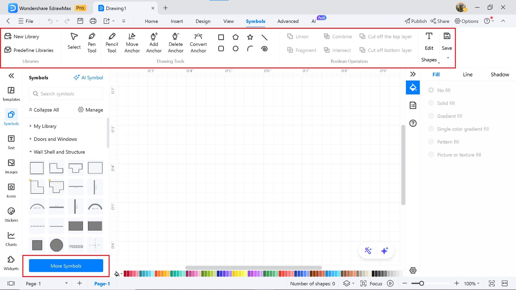
In this section, I will guide you through a floor plan-making software called EdrawMax. It is a recommended tool for drawing beam plans and other related diagrams. It is an easy and flexible tool designed for drafting and drawing work, developed and designed by WonderShare.
We will introduce vital features of EdrawMax for creating a beam plan, which can help you understand the building structure.
Import from Other Programs: EdrawMax allows you to import data from other software, such as CAD. This feature helps you import and edit different beam plan diagrams on EdrawMax. Most beam plans are planned according to the floor plan, so this feature allows you to smoothly exchange files with individuals who use CAD software.

Shape and Symbols: EdrawMax has 26000 symbols and elements, which can help you edit your beam plan. These symbols speed up the process and eliminate the steps for creating a diagram from scratch.
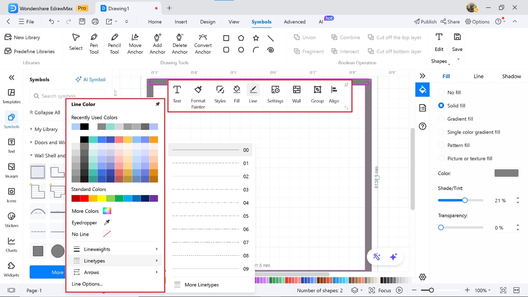
Lines Feature
Dotted lines are needed to display beams, and with EdrawMax, you can change the width and type of lines after choosing a symbol or shape. This helps you highlight the beams in the plan.
Select the symbol, and click > Lines Types or Lines Weights to change it. Not only this, but you can also change the colors for a unique diagram.
These are just a few valuable features available, with even more to explore.
Additionally, a wide selection of basic drawing templates is available for reference, making the process easier.
Try EdrawMax for a rich experience with comprehensive tools and features.
Summary
This article covers beam plans, including how to draw them, their key symbols, and how to interpret them. Beam plans are critical for delivering detailed structural layouts, optimizing construction efficiency, and ensuring building safety and stability.
Understanding methods like wooden post-and-beam construction is vital for creating clear and accurate beam plan diagrams. Explore the details above to grasp the essentials and significance of beam plans.
AI Diagram Generator
Enter your prompt. Upload files if needed. Generate diagrams, charts, or slides instantly.


