A process control system is a kind of system that keeps the parameters at a set level. These parameters include heating, cooling, pressure, and force. The industrial use of such systems is more prominent. Most advanced home appliances also use these systems, especially thermostats, where the room temperature is maintained at a specific level.
In this guide, you will learn all the insights of a process control system through process control system block diagrams. You will also learn about the methods involved in drawing such block diagrams.
In this article
What is a Process Control System?
The process control system is run by special sensors that automatically work to ensure the set parameters are obtained. A user doesn't need to set it up again and again. The system always uses the sensor to monitor the parameters, and when any of the set parameters are changed, it turns the system on or off automatically.
The industrial use of such a system brings many benefits to the business owners, and the system is run through automation. Certain elements are involved in this process to happen successfully; we will discuss them all individually through block diagrams.
Block Diagram for Process Control System
Here is a block diagram for the process control system where the system's working is explained. Let's check out the main components of the diagram.
There are three main components of a Process control system.
Sensor
A Sensor is the most important part of the Process control system. It detects physical quantities like temperature, water flow, heat, gas, pressure force, etc. It detects these quantities and converts them into an electrical signal for further operations.
Controller
The signal from the sensor is detected by the controller and processed there. After processing, the signal is sent to the actuator to produce an output.
Actuator
This actuator is a device that sends the feedback and converts the electric signal to a physical action like turning on the AC/ Heater, opening or closing the valve for water flow, or increasing or reducing the pressure in a chamber.
Types of Process Control Systems
Process control systems are of many types, as different types of systems are needed to perform different tasks. Here are a few of the types of process control systems.
Open Loop/Closed Loop Control Systems
An open-loop control system is a system where the system's performance does not influence output. The input of these open-loop systems work
A process control system is a kind of system that keeps the parameters at a set level. These parameters include heating, cooling, pressure, and force. The industrial use of such systems is more prominent. Most advanced home appliances also use these systems, especially thermostats, where the room temperature is maintained at a specific level.
In this guide, you will learn all the insights of a process control system through process control system block diagrams. You will also learn about the methods involved in drawing such block diagrams.
In this article
What is a Process Control System?
The process control system is run by special sensors that automatically work to ensure the set parameters are obtained. A user doesn't need to set it up again and again. The system always uses the sensor to monitor the parameters, and when any of the set parameters are changed, it turns the system on or off automatically.
The industrial use of such a system brings many benefits to the business owners, and the system is run through automation. Certain elements are involved in this process to happen successfully; we will discuss them all individually through block diagrams.
Block Diagram for Process Control System
Here is a block diagram for the process control system where the system's working is explained. Let's check out the main components of the diagram.
There are three main components of a Process control system.
Sensor
A Sensor is the most important part of the Process control system. It detects physical quantities like temperature, water flow, heat, gas, pressure force, etc. It detects these quantities and converts them into an electrical signal for further operations.
Controller
The signal from the sensor is detected by the controller and processed there. After processing, the signal is sent to the actuator to produce an output.
Actuator
This actuator is a device that sends the feedback and converts the electric signal to a physical action like turning on the AC/ Heater, opening or closing the valve for water flow, or increasing or reducing the pressure in a chamber.
Types of Process Control Systems
Process control systems are of many types, as different types of systems are needed to perform different tasks. Here are a few of the types of process control systems.
Open Loop/Closed Loop Control Systems
An open-loop control system is a system where the system's performance does not influence output. The input of these open-loop systems works on the predetermined rules.
In a closed-loop control system, feedback is used to compare the output needed to run the system. Input is used to fill the gaps between the outputs or eliminate any errors in the system.
Continuous/ Discrete Control Systems
The type of systems that operate to achieve a certain output value or time are called Continuous Control systems. These systems, like temperature control systems, are used in applications where continuous operation is needed.
Discrete Control systems are where the output is needed at certain points or time frames. These systems are usually used in machine control systems.
Linear/Nonlinear Control Systems
Linear differential equations represent linear control systems. The system's output is directly related to the system's input. They are easier to control and don't require specialized tools.
Nonlinear control systems are difficult to operate as the output is not dependent on the input. You may need special instruments and digital analyzers to operate these systems.
Single to Single/Multiple to Multiple control Systems
A system with a signal input and a single output is called a Single Input, Single Output Control System (SISO). These systems are very easy to operate due to their simple form. These systems are used in basic control systems and don't need a controller to control the system as it runs independently.
The type of system where multiple inputs and outputs are used is called a multiple input multiple output (MIMO) system. These systems are not easy to handle as they need complex integrations to control. However, they are being used at industrial levels where such systems are needed. However, the manual operation of such a system is difficult. So, an operator is needed to keep a look at the system.
How to Draw Such a Block Diagram?
Block diagrams are usually drawn using the two methods given below. One is from scratch, and the other one uses a template. We will discuss them one by one.
Method 1: Starting From Scratch
EdrawMax allows you to move things around on the canvas and use all the elements needed to draw a block diagram. Here are the steps you need to follow to draw a block diagram from scratch.
Step 1: Download EdrawMax or open it if you already have it on your computer.
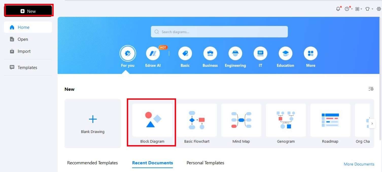
Step 2: Click New project and select Block diagram/blank drawing.
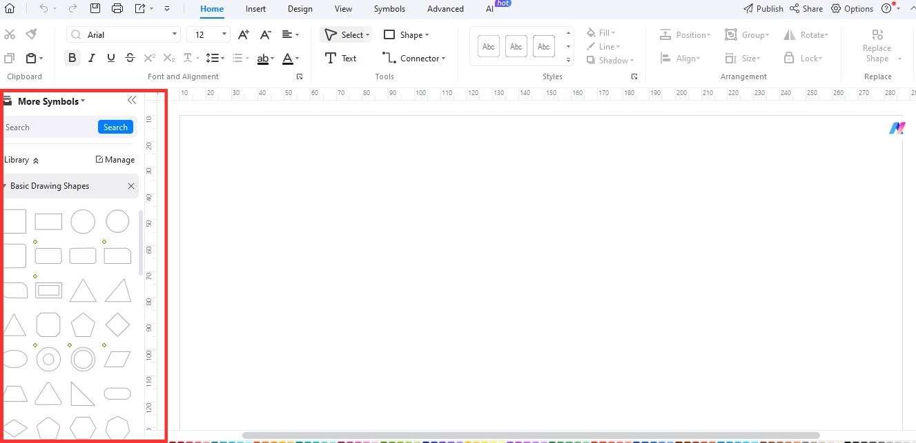
Step 3: Make use of the symbols and blocks given on the left side of the screen and drag them to the canvas. Click the symbol, hold it, and leave it on the canvas where you want to place it.
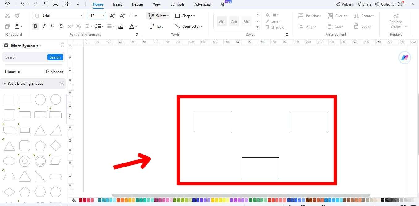
Now, drag elements from these symbols.
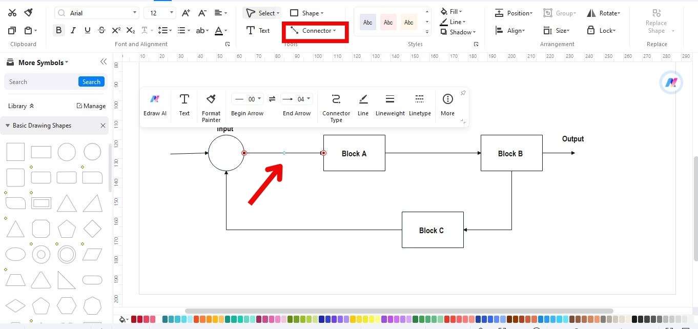
Step 4: Label the blocks. Adjust the sizes of these blocks or other elements you've dragged on the canvas and connect those blocks with the help of the connector on top of the screen.
Step 5: Add colours to the blocks or elements added. You only need to pick colours from the bottom of the screen and add them to the blocks.

Step 6: Add a background to make it look better, or upload your picture if you want your background.

That's it. Your block diagram is ready to get printed. You can also download multiple formats if you want to keep a soft copy.
Method 2: Start with a Template
Creating a block diagram from scratch is easier, but if you want to make your work even faster, you have the facility to use a template to start with. It is a super-fast and easy method, even for non-professionals. Here is what you need to do to begin with a template.
Step 1: Open EdrawMax, click Templates, and search “block diagram”.
Step 2: You will find hundreds of block diagram templates.
Step 3: Pick one of the templates of your choice. Move your cursor to the desired template and click use immediately.
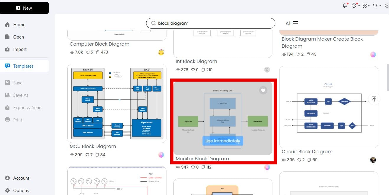
Step 4: Use your template and make your diagram by deleting all the unwanted blocks or elements from your chosen template.

Step 5: Add as much information as needed to make your block diagram and put the connections correctly among all the blocks.

You'll get the desired diagram in minutes. It’s amazing and super easy to draw a diagram with a template.
Conclusion
The process control system is best understood through a block diagram. There could be different block diagrams for different systems. Water flow, heater, and cooling systems are the main applications for these systems. You can draw your diagram according to the systems used. However, the method to draw block diagrams for the process control system is the same.
EdrawMax is where you can find all the necessary tools to make such block diagrams. So, what are you waiting for? Get EdrawMax and make your block diagrams yourself in the easiest ways possible.
s on the predetermined rules.
In a closed-loop control system, feedback is used to compare the output needed to run the system. Input is used to fill the gaps between the outputs or eliminate any errors in the system.
Continuous/ Discrete Control Systems
The type of systems that operate to achieve a certain output value or time are called Continuous Control systems. These systems, like temperature control systems, are used in applications where continuous operation is needed.
Discrete Control systems are where the output is needed at certain points or time frames. These systems are usually used in machine control systems.
Linear/Nonlinear Control Systems
Linear differential equations represent linear control systems. The system's output is directly related to the system's input. They are easier to control and don't require specialized tools.
Nonlinear control systems are difficult to operate as the output is not dependent on the input. You may need special instruments and digital analyzers to operate these systems.
Single to Single/Multiple to Multiple control Systems
A system with a signal input and a single output is called a Single Input, Single Output Control System (SISO). These systems are very easy to operate due to their simple form. These systems are used in basic control systems and don't need a controller to control the system as it runs independently.
The type of system where multiple inputs and outputs are used is called a multiple input multiple output (MIMO) system. These systems are not easy to handle as they need complex integrations to control. However, they are being used at industrial levels where such systems are needed. However, the manual operation of such a system is difficult. So, an operator is needed to keep a look at the system.
How to Draw Such a Block Diagram?
Block diagrams are usually drawn using the two methods given below. One is from scratch, and the other one uses a template. We will discuss them one by one.
Method 1: Starting From Scratch
EdrawMax allows you to move things around on the canvas and use all the elements needed to draw a block diagram. Here are the steps you need to follow to draw a block diagram from scratch.
Step 1: Download EdrawMax or open it if you already have it on your computer.
Step 2: Click New project and select Block diagram/blank drawing.

Step 3: Make use of the symbols and blocks given on the left side of the screen and drag them to the canvas. Click the symbol, hold it, and leave it on the canvas where you want to place it.

Now, drag elements from these symbols.

Step 4: Label the blocks. Adjust the sizes of these blocks or other elements you've dragged on the canvas and connect those blocks with the help of the connector on top of the screen.

Step 5: Add colours to the blocks or elements added. You only need to pick colours from the bottom of the screen and add them to the blocks.

Step 6: Add a background to make it look better, or upload your picture if you want your background.

That's it. Your block diagram is ready to get printed. You can also download multiple formats if you want to keep a soft copy.
Method 2: Start with a Template
Creating a block diagram from scratch is easier, but if you want to make your work even faster, you have the facility to use a template to start with. It is a super-fast and easy method, even for non-professionals. Here is what you need to do to begin with a template.
Step 1: Open EdrawMax, click Templates, and search “block diagram”.
Step 2: You will find hundreds of block diagram templates.
Step 3: Pick one of the templates of your choice. Move your cursor to the desired template and click use immediately.

Step 4: Use your template and make your diagram by deleting all the unwanted blocks or elements from your chosen template.

Step 5: Add as much information as needed to make your block diagram and put the connections correctly among all the blocks.

You'll get the desired diagram in minutes. It’s amazing and super easy to draw a diagram with a template.
Conclusion
The process control system is best understood through a block diagram. There could be different block diagrams for different systems. Water flow, heater, and cooling systems are the main applications for these systems. You can draw your diagram according to the systems used. However, the method to draw block diagrams for the process control system is the same.
EdrawMax is where you can find all the necessary tools to make such block diagrams. So, what are you waiting for? Get EdrawMax and make your block diagrams yourself in the easiest ways possible.
