


Are you looking for an easy way to create a component diagram in Visio? This article provides simple steps and useful tips for designing effective diagrams using both Visio and EdrawMax.
How do you make sense of your software components? UML component diagrams are key in software development. They show how different parts of a system connect. These diagrams are vital for understanding, designing, and documenting software.
In this article
Introduction to Visio
Many turn to Microsoft Visio to create component diagrams, but it can be tricky. Visio's complexity often makes it hard to create component diagrams smoothly. This is where EdrawMax shines. It's a user-friendly alternative that simplifies the process.
How to Create a Component Diagram in Visio?
Step 1. Create a New Component Diagram
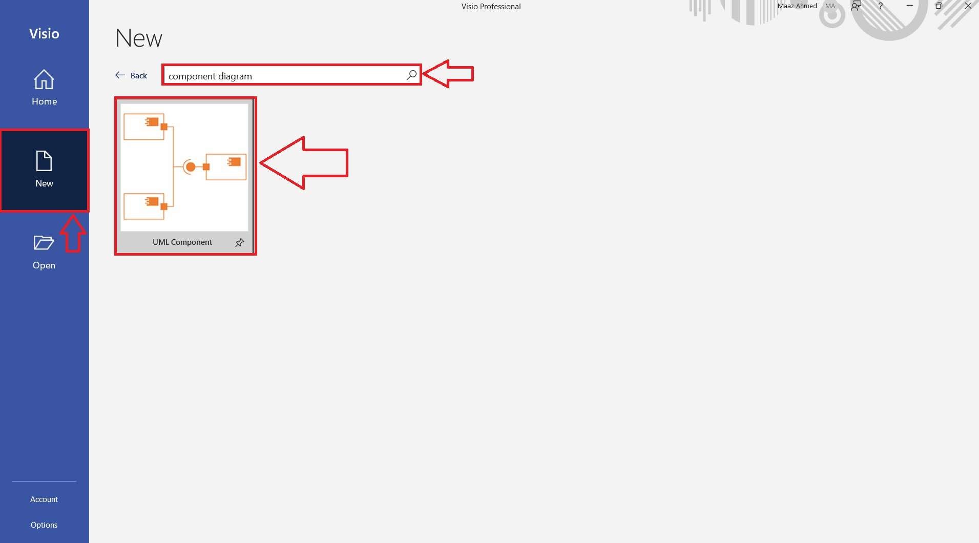
To begin, open Microsoft Visio. Navigate to the File menu and select New. In the search bar, type Component Diagram, and press Enter.
From the search results, choose the UML Component Diagram template. This will provide a suitable canvas and tools to start creating your component diagram.
Step 2. Select Units
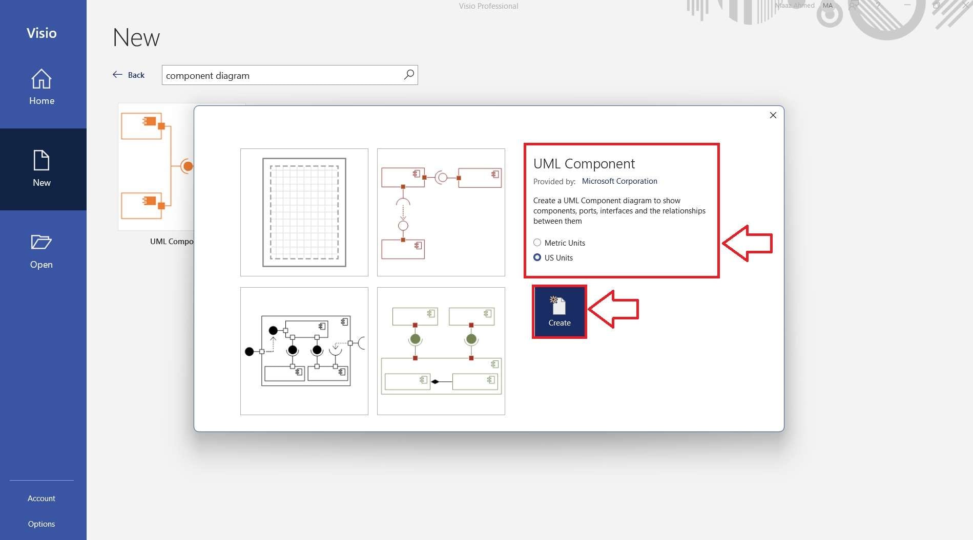
After selecting the UML Component Diagram template, you'll need to choose the unit system that suits your needs.
You can pick either US Units or Metric Units. Once you've made your selection, click on the Create button to open a new diagram canvas. This setup process is crucial for ensuring your diagram is created with the correct standards.
Step 3. Populate Your Component Diagram with Shapes
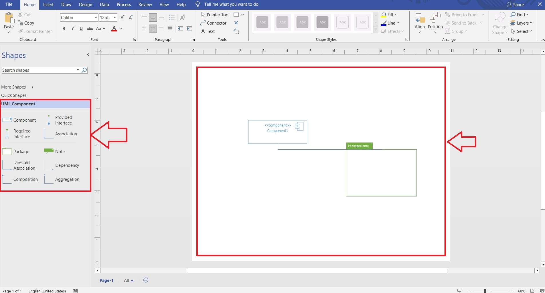
On the left side of the Visio interface, you'll find a panel with various UML component shapes. Browse through these available shapes to find the ones you need.
To add a shape to your diagram, simply drag it from the panel and drop it onto your workspace. Arrange the shapes according to your design requirements.
Step 4. Check Connection Points for Better Clarity
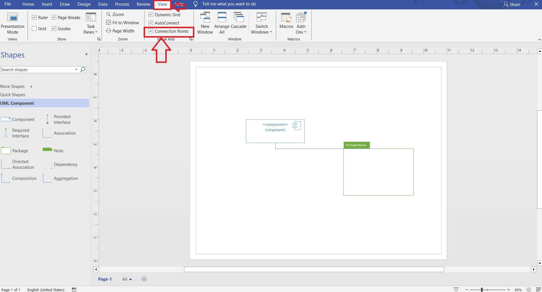
Navigate to the View tab at the top of the Visio interface. Here, you need to check the Connection Points option.
Enabling this feature will allow you to see all the connection points on the shapes in your component diagram. This step is essential as it helps you understand how different components are linked.
Step 5. Save or Export Your Diagram
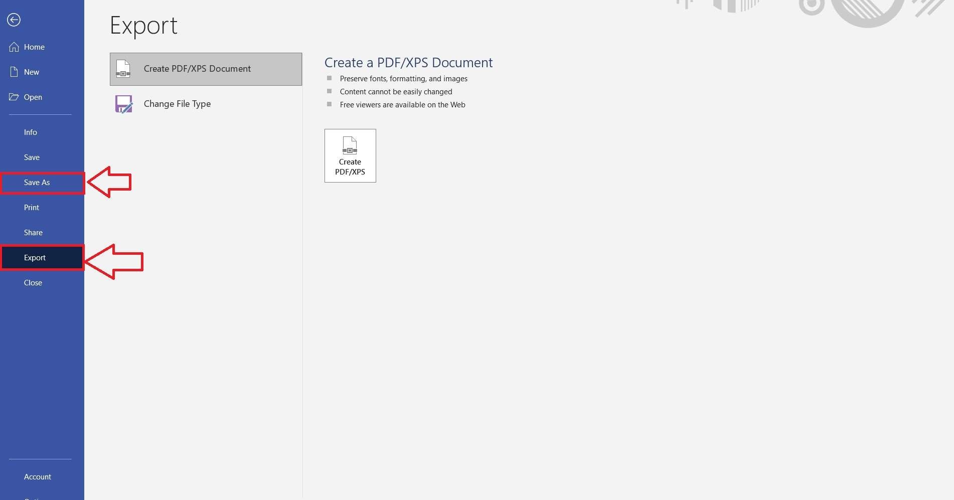
Once your component diagram is complete, it's time to save or export your work. From the dropdown menu, choose either Save As to store the diagram on your local drive or Export to create a PDF or another file format. Select the preferred format and follow the prompts to complete the process.
Common Difficulties When Using Visio
Using Visio to create component diagrams can present several challenges.
- First, the complexity of the interface can be overwhelming for new users. This makes it difficult to navigate and use the software effectively.
- Additionally, Visio requires a certain level of technical knowledge, which can be a barrier for some.
- Users often struggle with customizing templates and shapes to fit their specific needs.
- Moreover, the software can be resource-intensive, causing performance issues on less powerful computers.
These difficulties can make the diagramming process frustrating and time-consuming.
Introduction to EdrawMax
EdrawMax makes creating component diagrams easy and efficient. Its simple interface is perfect for beginners.
It lets you start working on your diagram quickly without any fuss. With a wide range of templates and shapes, customization is straightforward. Unlike Visio, EdrawMax uses fewer resources, so it runs smoothly on most computers.
How to Make a Component Diagram in EdrawMax
Step 1. Start from Scratch
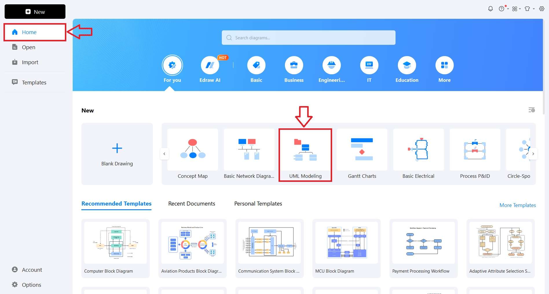
First, open the EdrawMax application on your computer. Navigate to the "Home" tab located on the left side of the screen.
In the "New" section, select the "UML Modeling" option. This will provide you with a blank canvas to start creating your component diagram. This setup will give you access to the tools needed for designing your diagram from scratch.
Step 2. Jumpstart with Template Community
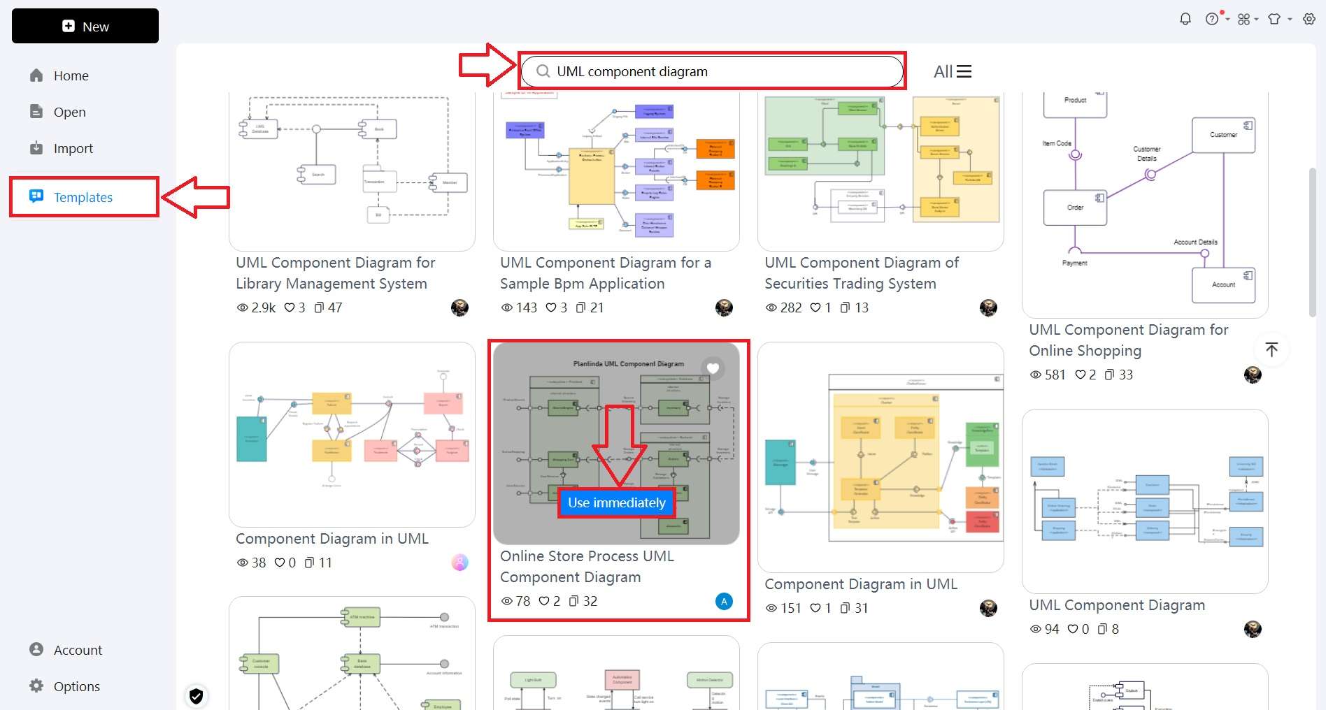
To quickly start your UML component diagram in EdrawMax, navigate to the Templates section.
In the search bar, type UML Component Diagram and Enter. Select the one that best suits your needs and click on Use Immediately. This will open the template for editing. This method saves time and provides a solid foundation for your diagram.
Step 3. Modify the Template
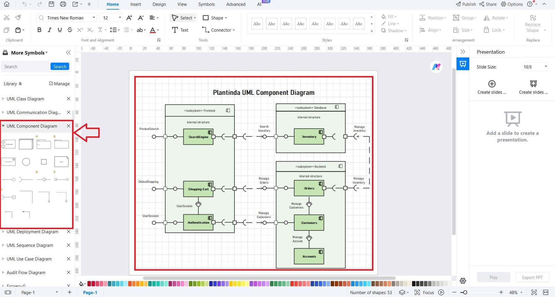
After picking a template, you can start customizing it. Use the available shapes in the UML component diagram section to modify the template.
Drag and drop these elements onto your canvas, and adjust their properties as needed. This allows you to tailor the diagram to accurately reflect your system's architecture. It ensures that all necessary components are represented.
Step 4. Enhance Your Component Diagram with the Floating Bar
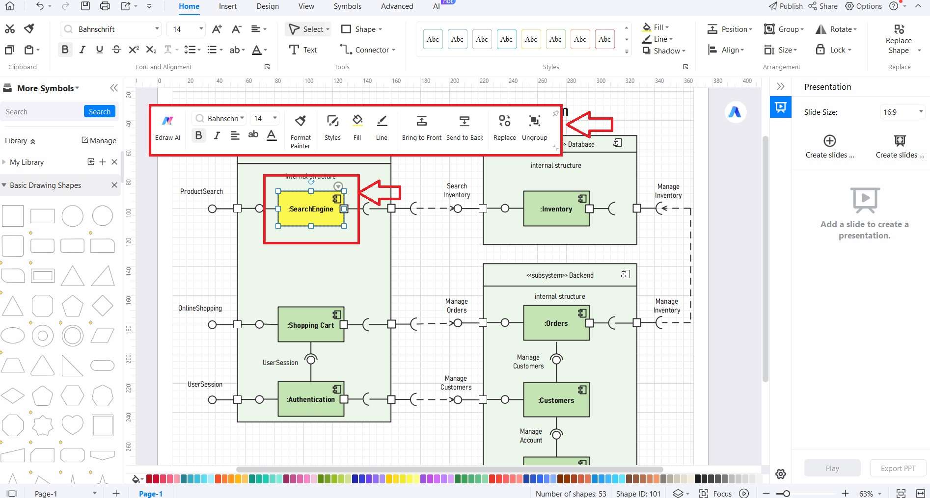
Use the floating bar in EdrawMax to quickly enhance your component diagram. This tool provides easy access to various formatting options, such as adjusting colors, fonts, and styles.
You can also bring elements forward or send them backward to organize your layout better.
Step 5. Finalize and Save Your Diagram
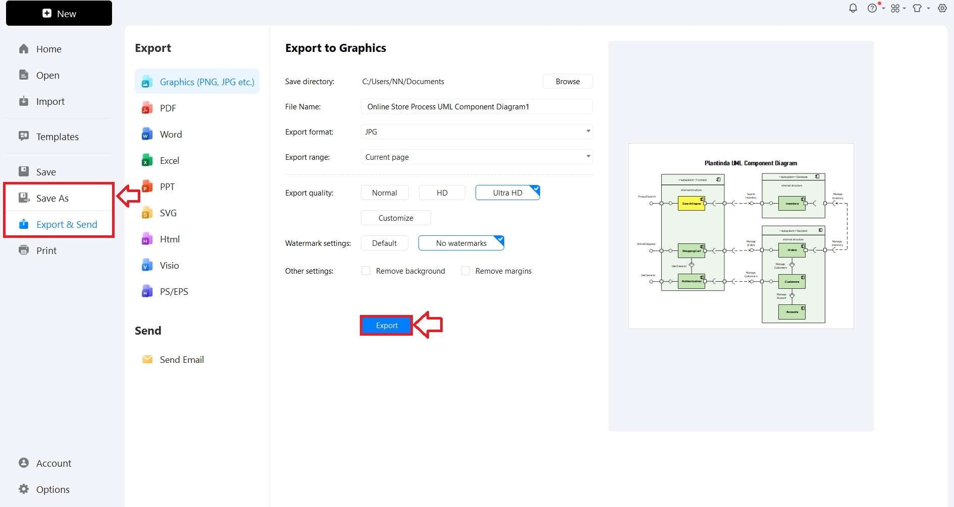
When you finish your component diagram, make sure to save or export your work. Navigate to the File menu, and choose Save As to keep a local copy of your design. Alternatively, use the Export & Send option to convert your diagram into formats like PDF, Word, or JPG.
Tips for Creating Effective Component Diagrams
Before starting your component diagram, it's essential to have a clear understanding of its purpose. Determine what you aim to convey through the diagram. It should effectively illustrate the various components of a system. Moreover, it should display how they interact, and the interfaces connecting them. By defining these elements, you ensure the diagram serves its intended function.
Clearly show how components connect and interact in your diagram. Use simple symbols and labels to mark dependencies, associations, and generalizations. This makes it easy to see the relationships between components. When these elements are well-defined, your diagram becomes more informative. It shows the structure and connections within the system.
Make your component diagram clear and easy to read. Avoid unnecessary details that can confuse viewers. Focus on showing only the key components and their relationships. Keep the diagram clean and uncluttered. This way, you can clearly show how the system works without overwhelming the audience. Simplicity helps in making the diagram more effective and useful as a reference.
Group related components into packages to keep your diagram simple and clear. This helps break down the system into smaller parts that are easier to understand. By grouping similar components, viewers can easily see their relationships and functions. This structure makes the diagram more effective in showing how the system works.
Show any external systems or services that your components interact with. Including these dependencies gives a clear picture of the system’s connections. This helps in understanding how your system integrates with others. Showing external dependencies ensures your diagram is complete and accurate. It makes your diagram more useful and informative.
Find the main parts of your system, like software modules and external systems. Focus on the most important ones to keep your diagram simple and clear. Highlighting these key parts helps viewers understand the system without getting overwhelmed. Keeping the focus on important elements makes your diagram easy to read.
Conclusion
Wrapping up, we've covered the steps to create detailed component diagrams using both Visio and EdrawMax. Microsoft Visio, while powerful, can be complex for some users. EdrawMax offers a more straightforward, beginner-friendly option with similar capabilities.
If you prefer to create component diagrams in Visio, follow the steps outlined to make the process smoother. Alternatively, you can create component diagrams online with EdrawMax, which provides an easier and more efficient experience. By following the tips provided, you can ensure your diagrams are clear, accurate, and easy to understand. Happy diagramming!
AI Diagram Generator
Enter your prompt. Upload files if needed. Generate diagrams, charts, or slides instantly.


