A Package Diagram is a UML (Unified Modelling Language) diagram that depicts the organization and dependencies of packages in a system. It shows how model pieces are organized into groups to represent the architecture or structure of a software system. These diagrams give a high-level overview of the system's structure, assisting stakeholders in understanding component organization and interactions. They help to manage complexity, improve communication between development teams, and ensure modular design.
The main idea behind developing package diagrams is to discover logical groups of related items and appropriately portray their relationships. This includes arranging components into coherent packages and outlining how they interact with one another. This article is about the UML package diagram tutorial.
In this article
What is a Package Diagram in UML?
Package Diagram has various elements of a system, such as classes, components, or other packages, are grouped into larger units called packages and how these packages depend on or relate to each other.
Notations and Symbols Used in a Package Diagram Include
Here are a few of the symbols and notations for the elements used in the package diagram. These symbols illustrate the structure and relationships within a system.
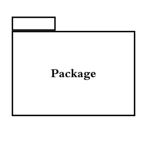
Package
The package is represented by a folder-like icon with the package name inside. It encapsulates related elements, such as classes, interfaces, or other packages, providing a level of abstraction and modularity to the system.
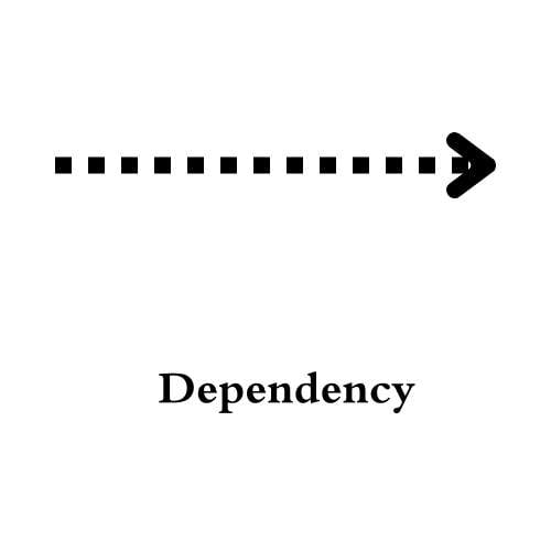
Dependency
Dependency is shown as a dashed arrow between packages, indicating that one package depends on another. Dependencies can be either directed or bidirectional, signifying the direction of the relationship.
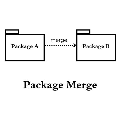
Package Merge
Package Merge is denoted by a solid arrowhead, it represents the merging of contents from one package into another. This symbol is used when two or more packages are combined to form a single package.
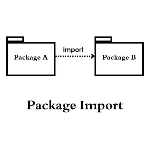
Package Import
Package Import is displayed as a dashed arrow with a triangle pointing to the package being imported, it signifies that elements from one package are imported into another without establishing a direct dependency between the two packages.
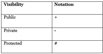
Package Visibility
This notation indicates the visibility of packages, whether they are public, private, protected, or package-private, using symbols such as a plus sign (+) for public visibility, a hash symbol (#) for protected visibility, a hyphen (-) for private visibility, and no symbol for package-private visibility.
How to Create a Package Diagram with EdrawMax?
EdrawMax offers several features that make it a versatile and powerful diagramming tool:
- Wide Range of Diagram Types: EdrawMax supports a vast array of diagram types, including flowcharts, organizational charts, mind maps, floor plans, network diagrams, and more.
- User-Friendly Interface: With its user-friendly interface, EdrawMax makes diagram creation accessible to users of all levels of expertise. Its drag-and-drop functionality, customizable templates, and extensive symbol libraries makes it easier for users to create diagrams faster.
- Collaboration and Compatibility: EdrawMax facilitates collaboration by allowing users to work on diagrams simultaneously with team members in real-time.
- Advanced Features and Customization Options: EdrawMax provides advanced features and customization options to meet the diverse needs of users.
- Thousands of Templates: EdrawMax offers thousands of free templates for users to work with. It helps them save a lot of time and work on the files and save them after editing their designs.
Here is a step-by-step guide to create a package diagrams through EdrawMax.
Step 1:
Open EdrawMax and navigate to the Software category or search for the package diagram in the template search bar. Choose the Package Diagram template to start a new drawing.
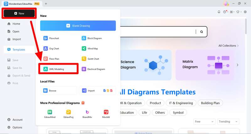
Image Name: open-edrawmax.jpg Image Alt: launch edrawmax and click uml modeling
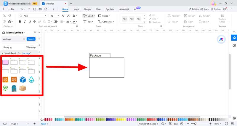
Step 2:
Drag and drop the Package shape from the library onto the drawing canvas to represent the main packages in your system. Double-click on the package shape to enter the name of the package.
Step 3:
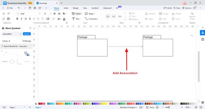
Use connectors (lines or arrows) to establish relationships between packages. Drag the connector shapes from the library and connect the packages by clicking and dragging from one package to another. You can use different types of connectors to represent different types of relationships, such as dependency, association, or package merge.
Step 4:
Customize the appearance of packages and connectors by adjusting their colors, line styles, and other formatting options. Add labels or annotations to clarify the relationships between packages if necessary. Save images and graphic files for further changes and improvements.
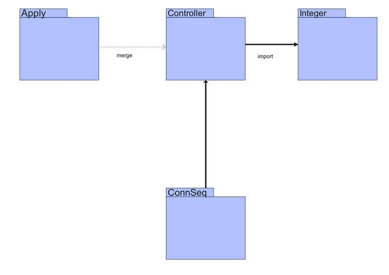
By following these four simple steps, you can create a package diagram in EdrawMax to illustrate the organization and dependencies within your software system effectively.
Conclusion
Package diagrams play a crucial role in visualizing the structure and dependencies within software systems. They help in communication and visualizing the complex system. So, they are of great importance when it comes to understanding and making further changes in the system.
EdrawMax offers an intuitive and comprehensive solution for creating package diagrams effortlessly. With its easy interface, extensive library of shapes and connectors, and collaborative features, EdrawMax enables users to design clear and informative package diagrams with ease.
Whether you're a software developer, architect, or project manager, EdrawMax provides the tools you need to effectively communicate the architecture of your system. I highly recommend EdrawMax for creating package diagrams in a natural and efficient way.


