Free circuit diagram maker
Design accurate and professional circuit diagrams in minutes with EdrawMax. Draw circuits using automatic connectors, built-in symbols, and an easy-to-use interface.
Why Use EdrawMax Circuit Diagram Maker?
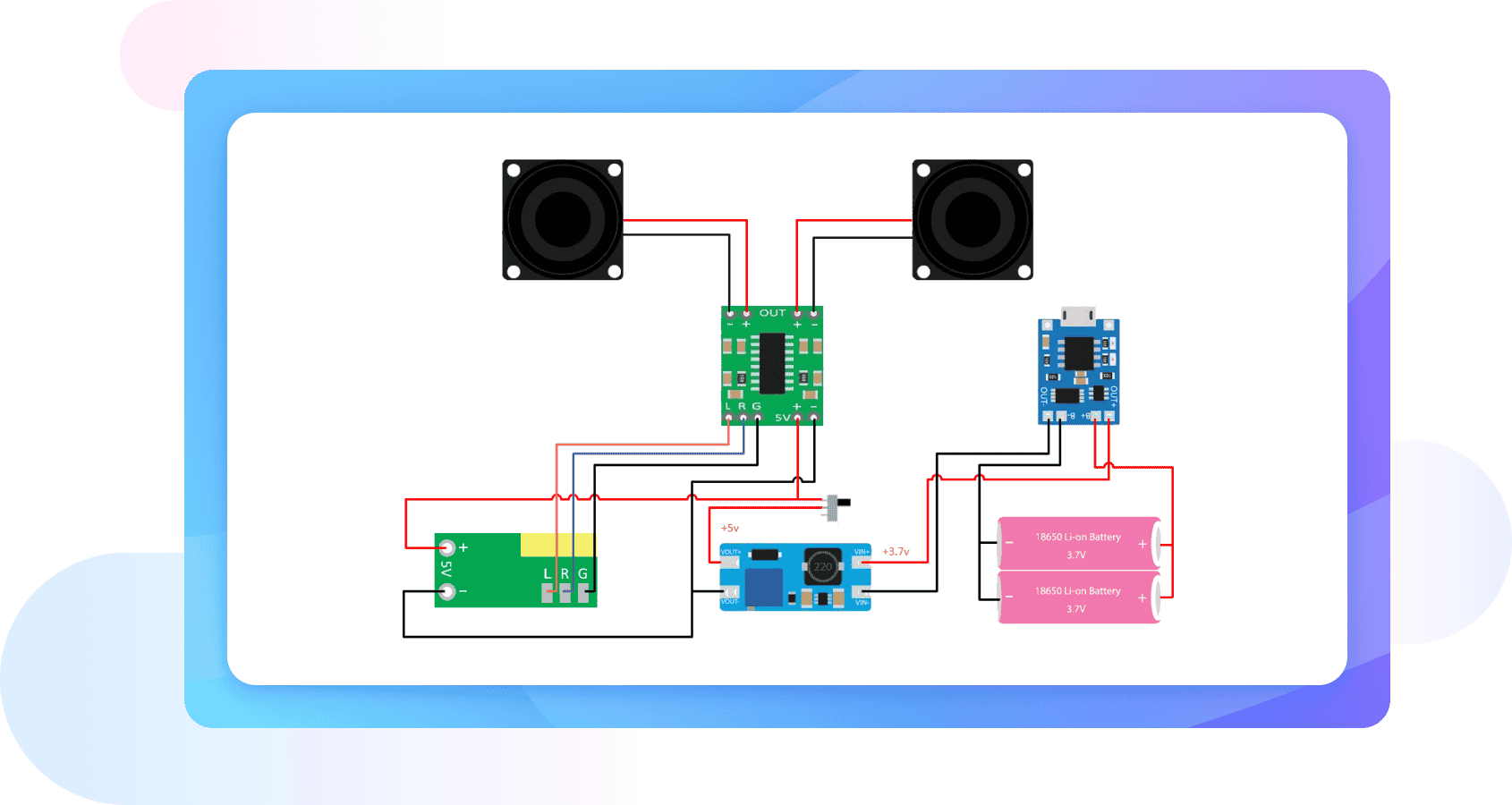
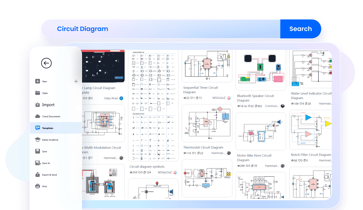
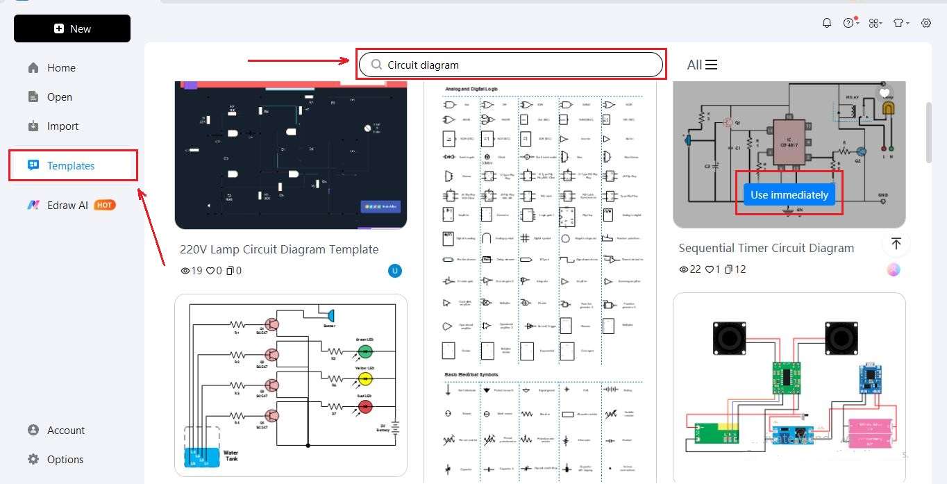
We know everyone deserves an easy start. That’s why EdrawMax gives you access to more than 25,000 ready-made templates. Whether it’s a simple circuit, a logic gate, or a complex design, you’ll find it here. Just select one, add your details, and customize it your way.
With one click, you can turn a simple circuit diagram into a polished, professional design. This tool cleans up spacing, applies consistent colors, and aligns everything neatly. You don’t need to spend time adjusting details. It makes your work look polished and ready to share in seconds.
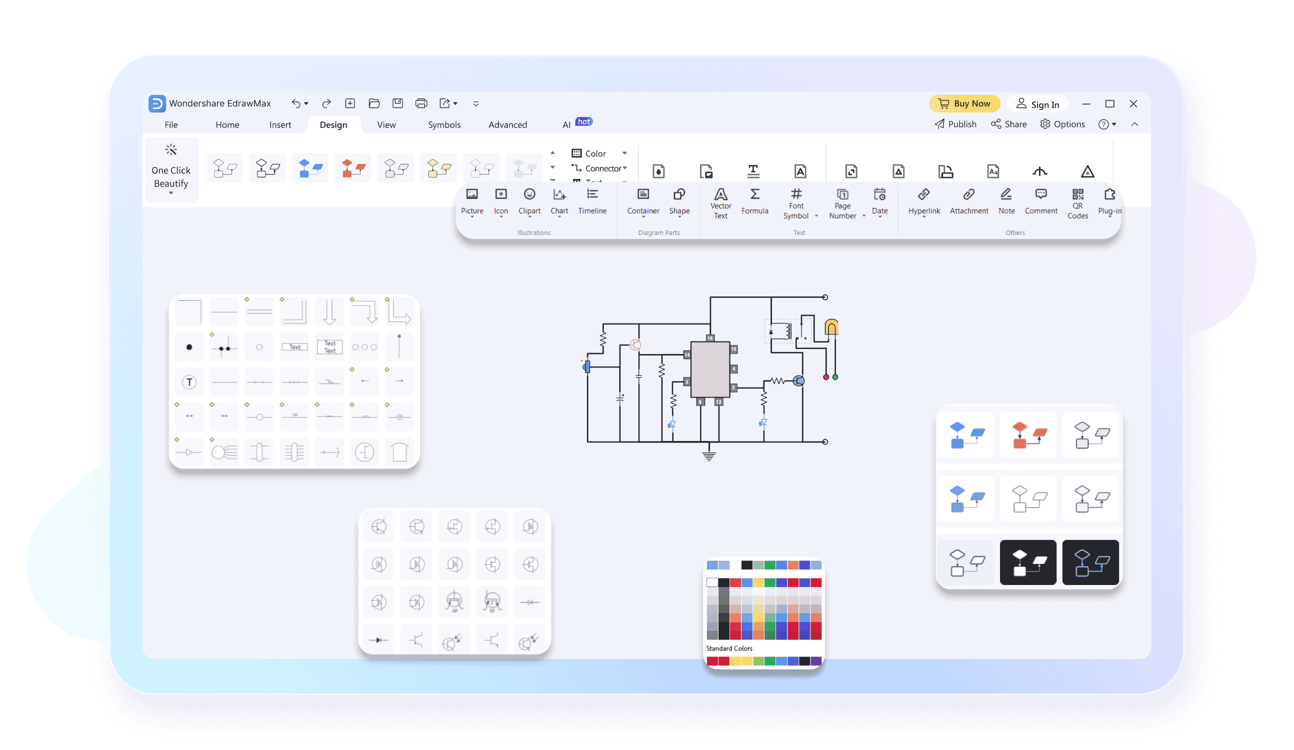
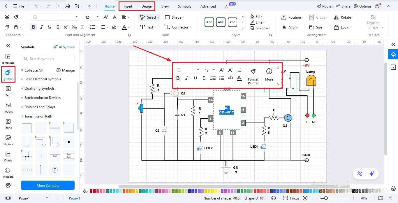
Symbols make the difference in circuit diagrams. EdrawMax gives you a huge library of circuit symbols. You'll find resistors, capacitors, switches, and so much more. Drop them onto the canvas, resize them without losing clarity, and create a clean diagram. You can even save your most-used symbols for later. It’s flexible and saves you time.

Work doesn’t have to stop when you switch devices. With EdrawMax’s cloud access, your diagrams are always saved and synced. Just log in from any computer, and your work is waiting for you. It’s like carrying your circuit toolbox everywhere. Always ready, always up to date.

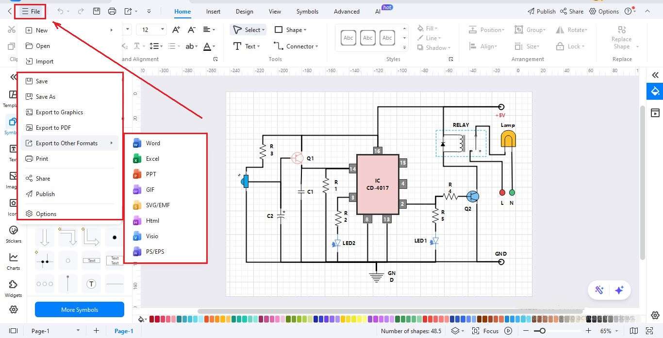
Finished your circuit? Sharing is simple. Export it as a PDF, PNG, or SVG with just a click. You can also generate a link to share with teammates, even if they don’t use EdrawMax. Printing, presenting, or sending your design takes just seconds, so collaboration is easy.

How to Make a Circuit Diagram in 3 Simple Steps
What our users say

More Circuit Diagram Tools
Discover more AI-powered diagram makers to boost your productivity.
FAQs About EdrawMax Circuit Diagram Tools
-
What is a circuit diagram?A circuit diagram is a visual representation of an electrical circuit using standardized symbols. It illustrates how various components, such as resistors, capacitors, and power sources, are interconnected. These diagrams serve as a blueprint for engineers and hobbyists to design, build, and troubleshoot electronic systems efficiently without needing physical pictures.
-
What are the most common symbols used in circuit diagrams?Common symbols include straight lines for wires, zig-zag lines for resistors, and two parallel lines for capacitors. A circle with a plus and minus sign typically represents a DC voltage source, while a battery is shown as alternating long and short lines. These universal symbols ensure clear communication across languages.
-
How can I tell the difference between series and parallel circuits in a diagram?In a series circuit, components are connected end-to-end in a single path, meaning current flows through each one sequentially. In a parallel circuit, components are connected across the same two points, creating multiple branches for current to flow. Look for "loops" to identify parallel sections versus a single continuous line.
-
How to read a complex circuit diagram?Start from the power source, typically found on the left or top of the diagram. Follow the path of the current through the components toward the ground or negative terminal. Identifying functional blocks, like the power supply or amplifier stage, helps break down complex designs into manageable, understandable sections.
-
What does a dot represent where two lines cross in a diagram?A solid dot at the intersection of two lines indicates a deliberate electrical connection or "junction" between those wires. If two lines cross without a dot, they are not connected and are simply passing over each other. This distinction is crucial for correctly interpreting how current moves through the system.
-
What is the purpose of including resistors in a circuit diagram?Resistors are depicted to show where electrical current is being limited or where voltage is being divided. They are vital for protecting sensitive components, like LEDs, from excessive current. In a diagram, their specific values are often labeled next to the symbol to guide the assembly and testing process.
Learn about Circuit Diagram
Stop drawing. Start describing.
AI diagramming isn't just text-to-diagram.
AI now understands any input, fetches live data, adapts through dialogue, and works everywhere.
 (AI & Web)
Free circuit diagram templates from EdrawMax