


This article describes the major elements and functionality of the buck converter and takes readers through modes of operation, design considerations, and protection strategies. It also demonstrates the fast process of developing a professional buck converter circuit diagram with EdrawMax.
- buck converter circuit diagram
- buck converter working
- buck converter design
- DC-DC step-down converter
The simplest circuit diagram of a step-down DC-DC step-down converter is a buck converter circuit diagram. It traces out switches, diodes, inductors, and capacitors such that you can trace the flow of energy. DC conversion efficiency is important in the current day. It can save battery, reduce heat, and enhance the reliability of systems in phones, IoT devices, and EVs.
This article takes you through the fundamentals of the practice. You will also get to know major elements and modes of operation, have real-life schematics to look at, and design advice. Then we will demonstrate an EdrawMax tutorial that allows you to draw, style, and export your own professional buck converter diagrams.
In this article
- Buck Converter Basics
- Key Components in a Buck Converter
- Working Principle Explained
- Buck Converter Circuit Diagram Examples
- How to Draw a Buck Converter Circuit Diagram in EdrawMax
- Buck Converter Block Diagram Examples
- How to Draw a Buck Converter Block Diagram in EdrawMax
- Create a Circuit Diagram Online Now
- Best Practices for Creating Accurate Designs
- Conclusion
Buck Converter Basics
A buck converter is a DC-to-DC step-down regulator. It reduces a greater input voltage to a constant reduced output voltage. It aims to efficiently convert the voltage of electronics that require lower voltages than the source.
The switching principle makes use of a type of electronic switch and energy storage elements. When the switch is on, the inductor stores the input energy. When the switch is off, the inductor dissipates energy to the load via a diode or MOSFET circuit.
A capacitor is used to remove the pulsed current of the inductor into a continuous DC voltage. This capacitor minimizes the voltage ripple and assists in maintaining the output constant during switching events and load variations.
Control logic adjusts the ratio of on/off (duty cycle) of the switch to adjust the average output voltage. A feedback loop measures the output voltage and regulates the duty cycle to provide regulation with underwhelming loads.
Common operational input ranges are between approximately 5 V and 48 V, based on the use. Outputs of the 1.2 V-24 V band are common. ICs and sensors have smaller point-of-load converters at the ends.
The efficiency of buck converters is far better than that of linear regulators. Current designs- particularly synchronous buck designs- can be over 90 per cent efficient. Increased efficiency translates into reduced heat, increased battery duration, and reduced thermal design requirements.
Key Components in a Buck Converter
A buck converter reduces a high voltage to a safer and lower voltage without wasting power. Its circuit is not very complex but intelligent. All the parts work to regulate the circulation of electricity and maintain the output constant.
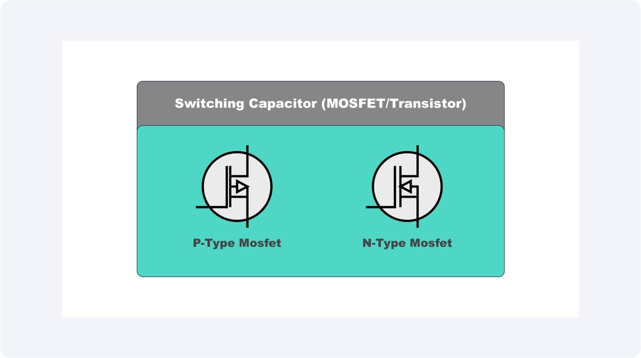
Switching Capacitor (MOSFET/Transistor)
This resembles an electronic gate that switches the power on and off rather fast. It can regulate the amount of energy passing on to the remainder of the circuit by switching between states at a high rate.
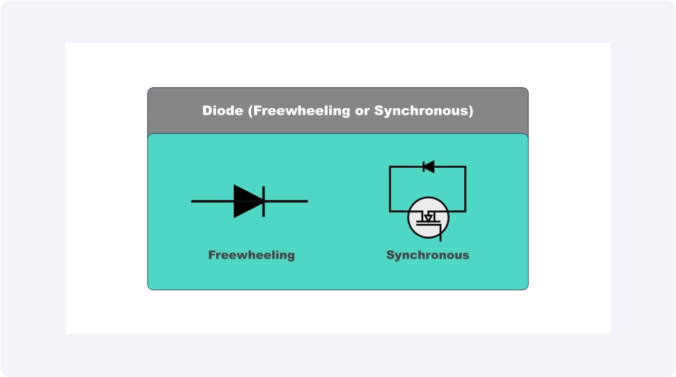
Diode (Freewheeling or Synchronous)
The freewheeling diode acts as a unidirectional conductor. When the switch is switched off, the diode allows electricity to continue flowing; thus, the power does not simply disappear after switching off.
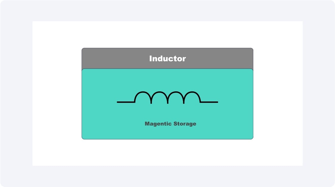
Inductor
You can compare an inductor to a small magnetic storage coil. It serves to store energy when the switch is on and to release it gradually when the switch is off, so that there are no sharp spikes or drops in voltage.
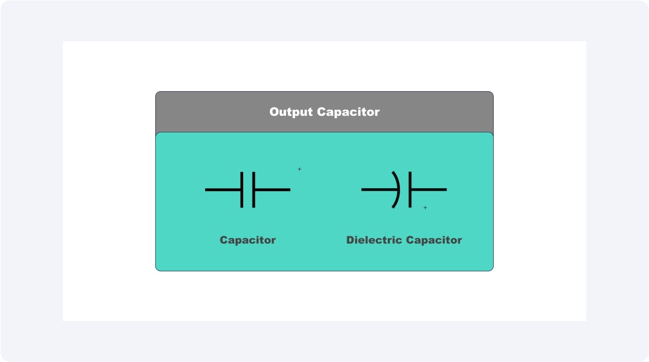
Output Capacitor
The capacitor is similar to a miniature storehouse of energy. It smooths out the ripples in the voltage, and the recipient of the power achieves a uniform and clean power output.
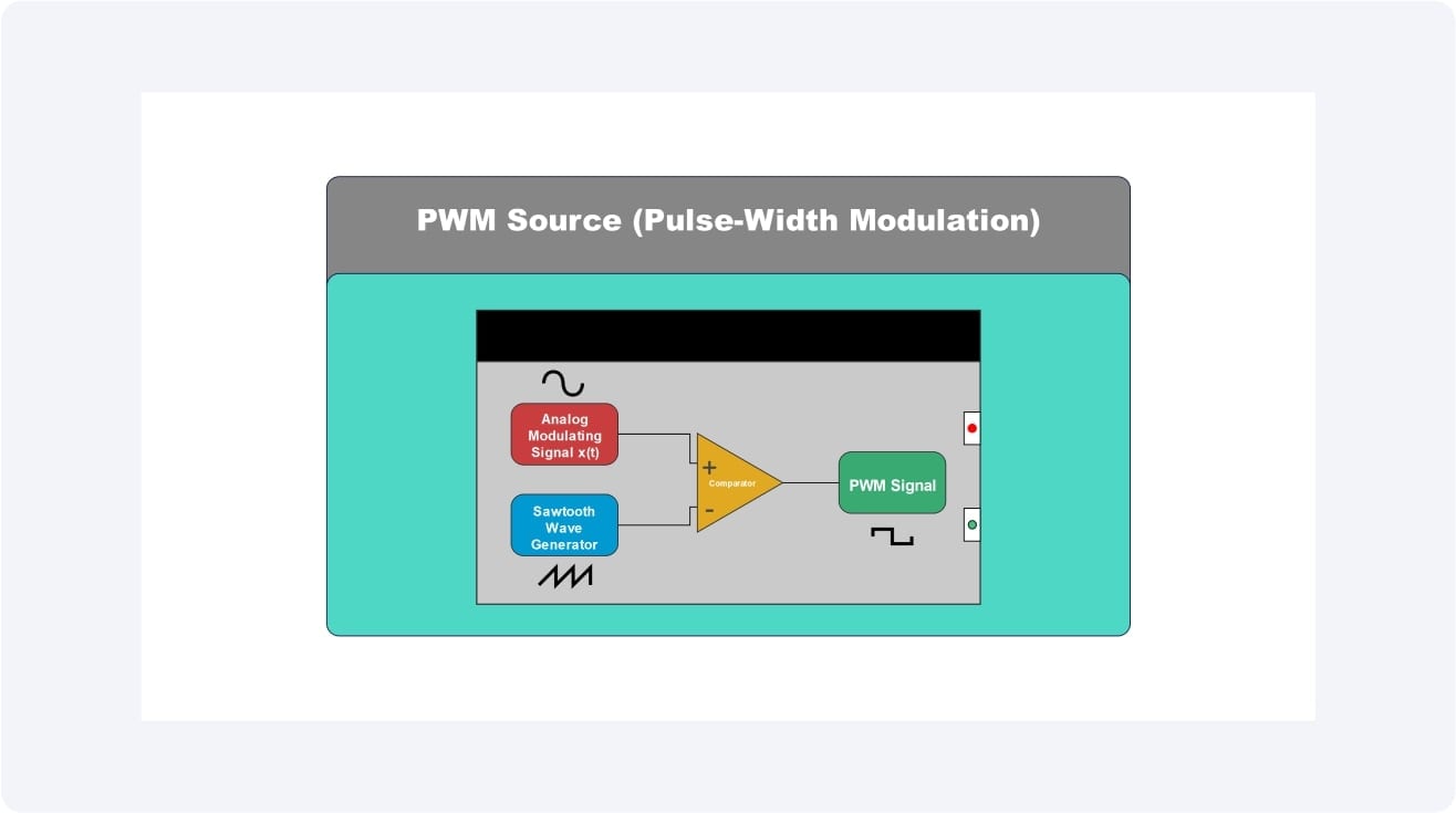
PWM Source (Pulse-Width Modulation)
This is the control brain. It gives accurate instructions to the switch, whether to keep it on or not. It regulates the final output voltage by modulating these pulses.
Working Principle Explained
Within a buck converter, power does not flow anywhere--power is timed and shaped. Through quick changing input voltage and energy storage of the inductor, the circuit converts a higher supply to a lower and constant output that is also the demand of other devices connected to it.
Continuous Conduction vs. Discontinuous Conduction
Continuous Conduction
The level of the inductor current never returns to zero. The energy passes uninterrupted, and thus, this mode is effective in constant loads.
Discontinuous Conduction
Between switching cycles, the current in the inductor momentarily goes through zero (typically when the load is light or when the input voltage is large ).
Discharge and Charge Cycle of the Inductor
With the switch on, the current is able to run through the inductor, and it holds the energy within a magnetic field. With the switch off, this stored energy is released to the load through the diode by the inductor and maintains the output voltage constant.
Role of Duty Cycle
The percentage of time taken by the switch to remain ON during each cycle is known as the duty cycle. An increased duty cycle causes an increased amount of energy to be sent to the output, increasing the voltage. By reducing the duty cycle, the output voltage can be reduced to permit control.
Buck Converter Circuit Diagram Examples
Buck converters come in various designs, depending on their intended use. Although the fundamental concept remains the same, which is to decrease a greater DC voltage to a smaller but more controlled output, circuit type selection is influenced by factors such as efficiency, load size, and cost. We will consider two typical examples in which these converters are applied.
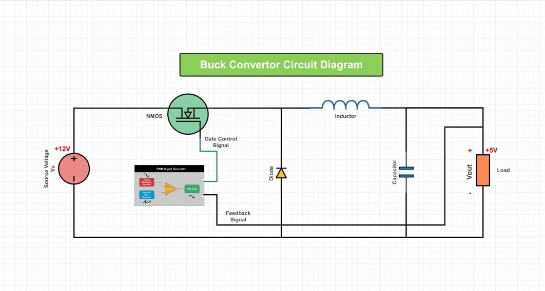
Example 1: Simple 12V to 5V Step-Down Converter
This is the most typical kind of buck converter. It is then fed by a 12V input (such as a car battery or power adapter) and reduced to 5V, which is suitable to power up devices such as microcontrollers, sensors, or USB-powered devices. It involves a simple circuit consisting of a switch, a diode, an inductor, and a capacitor. Its advantage is that it is simple and inexpensive to make.
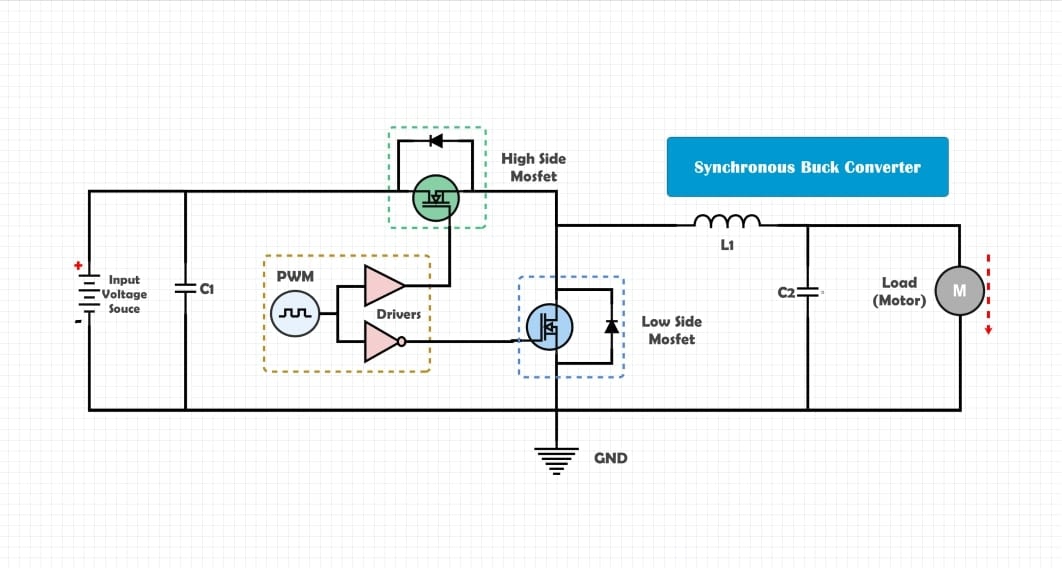
Example 2: Synchronous Buck Converter
Rather than employing a diode, this circuit employs another MOSFET (Low-Side FET) to enhance efficiency. With an active switch, less energy is lost, particularly at higher currents, by substituting the diode with the active switch. This renders synchronous buck converters popular in recent electronics such as laptops, smartphones, and servers, where power savings are paramount.
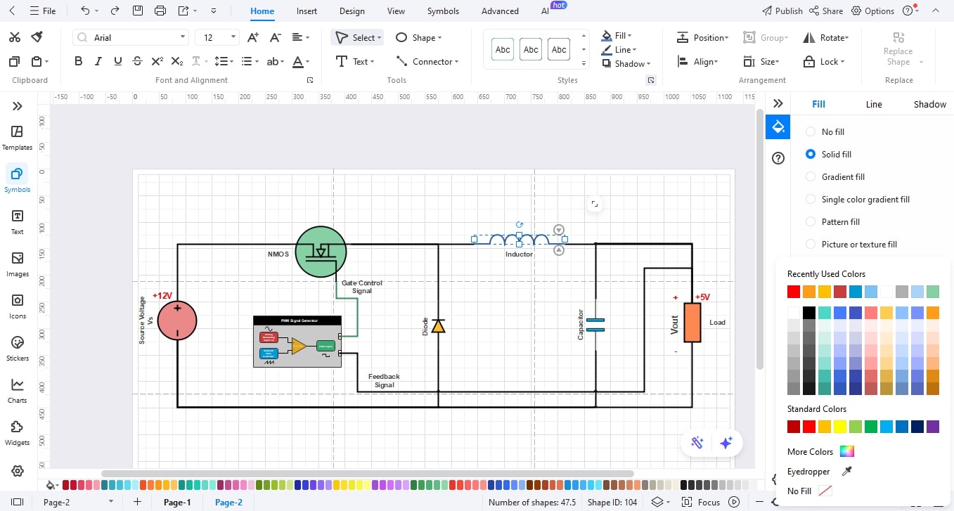
How to Draw a Buck Converter Circuit Diagram in EdrawMax
Designing a buck converter circuit setup can be a complex task, but it is easy using EdrawMax and pre-made electronic components, including convenient drag-and-drop features. You can easily draw every circuit element, switch, diode, inductor, and so on, and export a professional circuit diagram within minutes. Just follow these steps:
Step1 Make a New Project
- Open EdrawMax.
- Click New on the left panel.
- Select Blank Drawing to begin with a blank canvas.

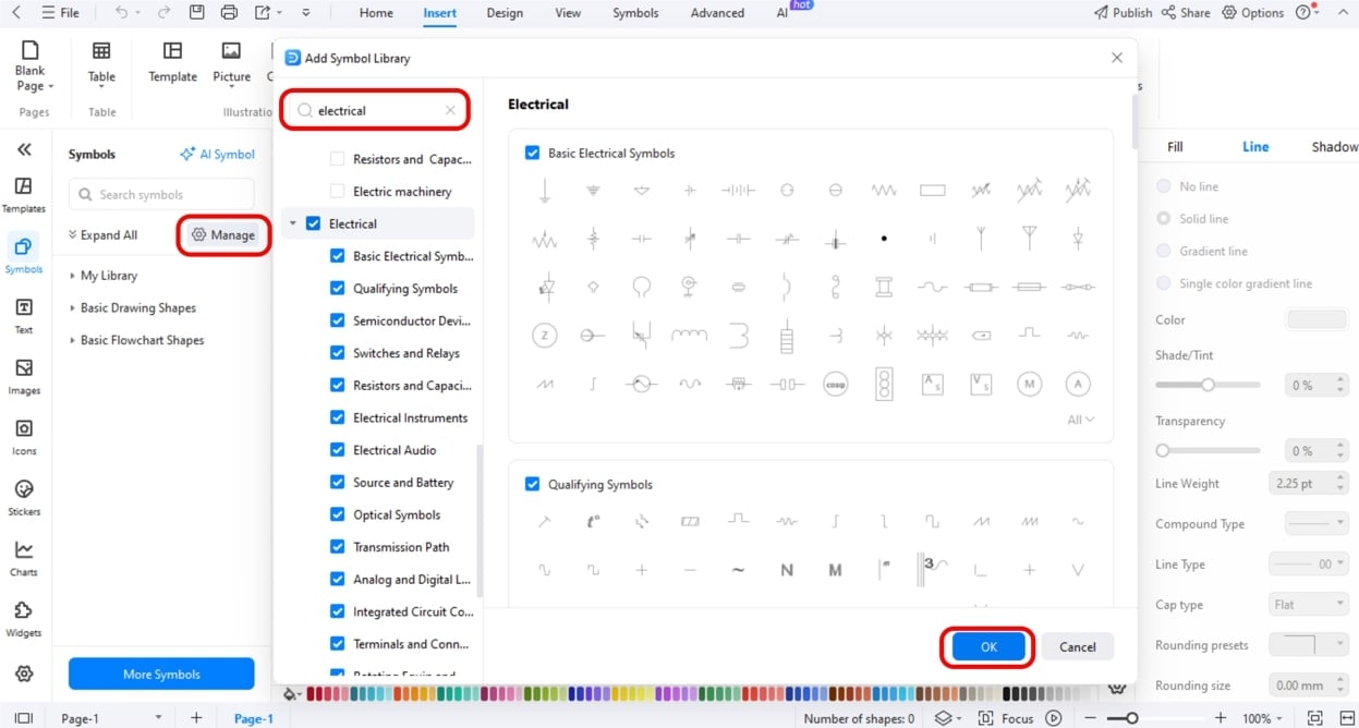
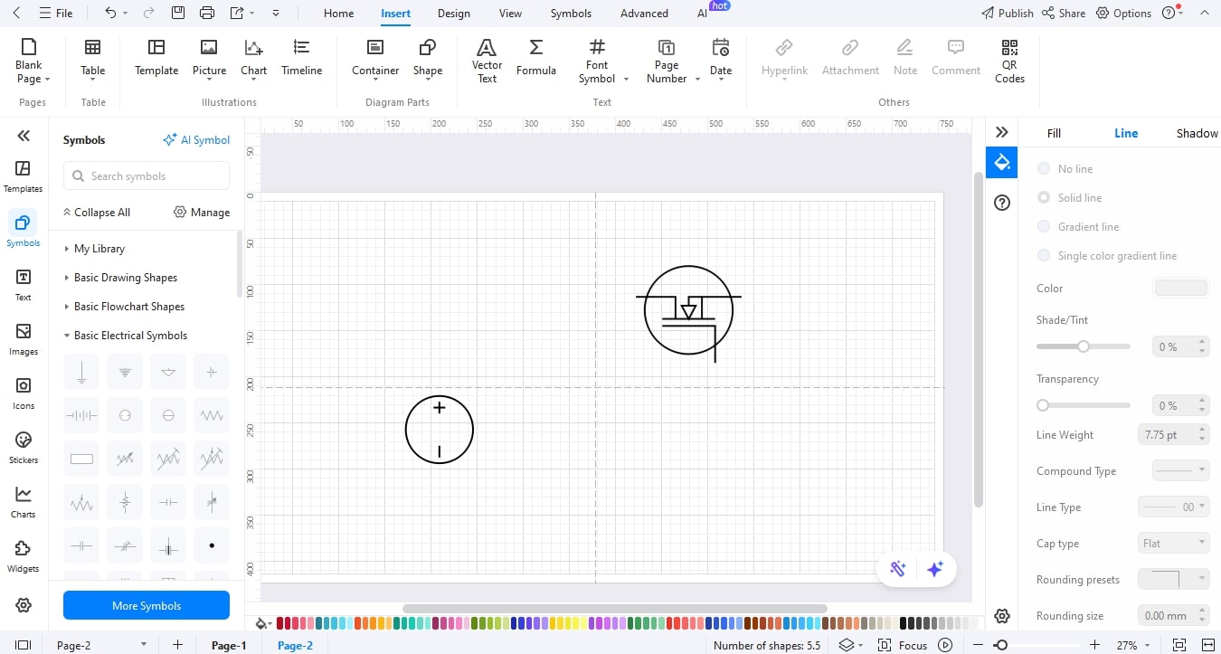
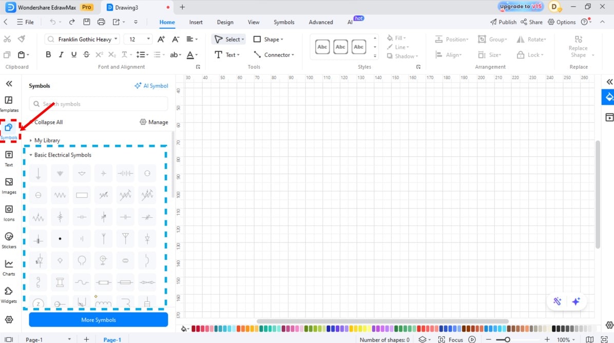
Step2 Select Electronic Symbol Libraries.
- Select the left toolbar of Symbols or More Symbols.
- Right-click Manage and then Add More Symbols.
- Add the Electrical or Circuit and Logic libraries to use such components as MOSFETs, diodes, inductors, and capacitors.
Step3 Trace the Power.
- Select a DC power source and drag it to the canvas using the symbol library.
- Add a MOSFET/Transistor symbol beside it, which is used to indicate the switching device that regulates the flow of energy.
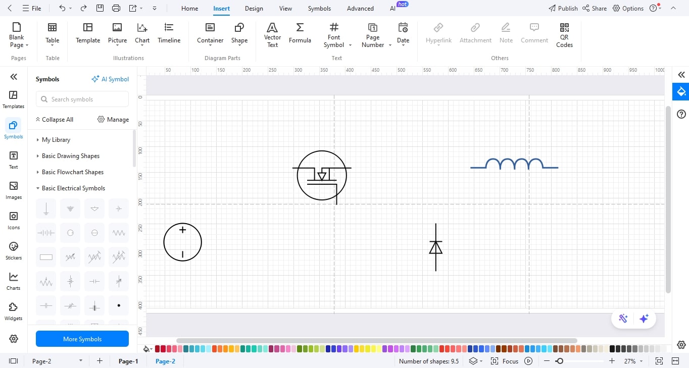
Step4 Add the Diode and Inductor.
- Add a Diode symbol for the freewheeling.
- Now, drag an Inductor symbol to show the coil containing the energy. Make them so that current flows through the diode and through the inductor.
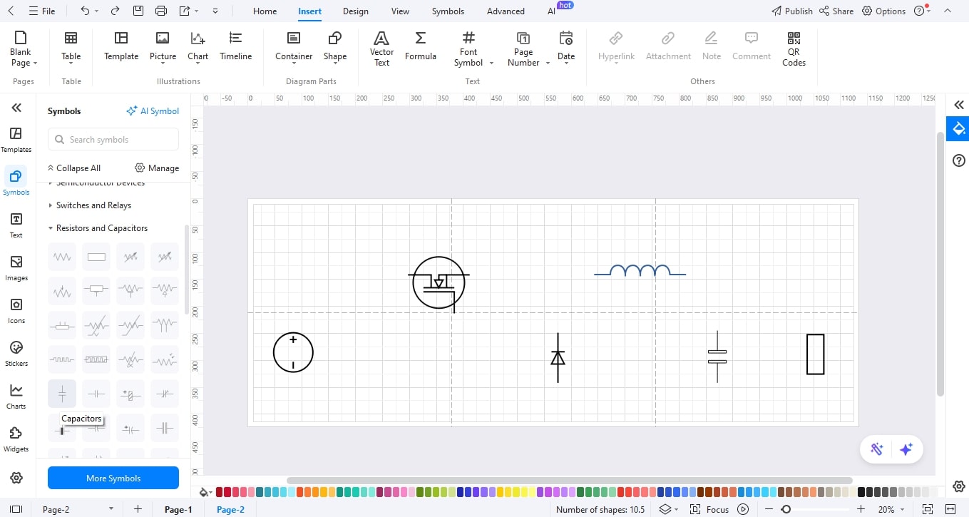
Step5 Add the Load and the Capacitor of the output.
- Symbolically place a Capacitor at the end of the inductor to regularise the voltage.
- Insert a Resistor or load symbol to indicate the output point of the converted voltage.
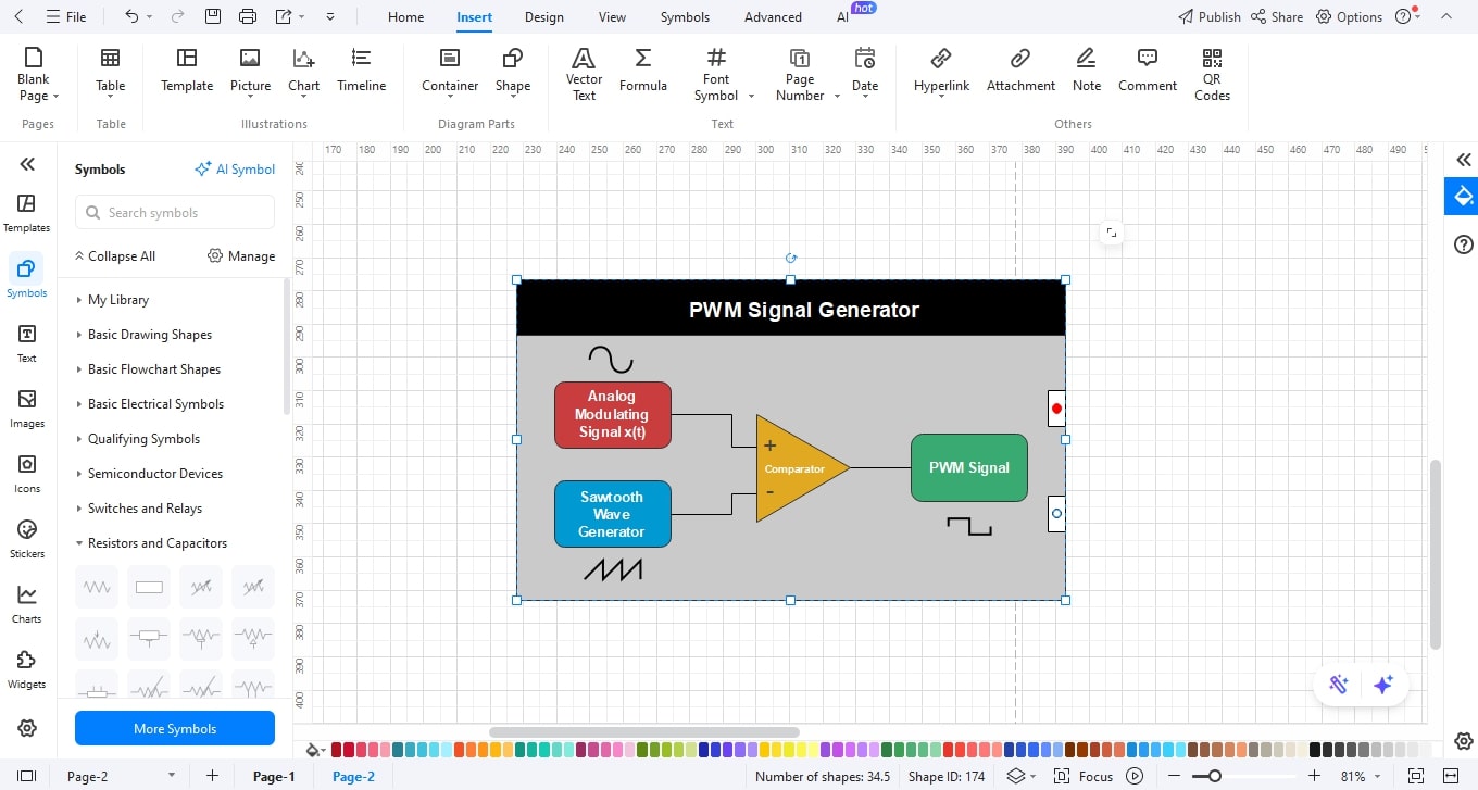
Step6 Add the PWM Control Source.
- To specify the source of the PWM signal.
- Drag a PWM signal icon or place a note on the switch, such as PWM Control.
Step7 Label, Style, and Attach Components to Wires.
- Name the parts (e.g., MOSFET, Diode, L).
- Change the colors of the desired element.
- Connect the wires by using the connector tool.
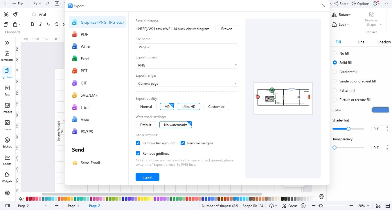
Step8 Export
- Finalise the diagram by checking the alignments and spacing to be clear.
- After that, save your design.
- Then export your diagram in the desired format (JPG, PNG, SVG, or PDF).
Buck Converter Block Diagram Examples
A circuit diagram shows the physical components (switch, inductor, capacitor) and their exact connections, while a block diagram uses functional modules (Power Stage, Controller, Feedback) to abstractly explain the system's operation and signal flow.
Now to help you to understand their difference further, let’s look at some examples.
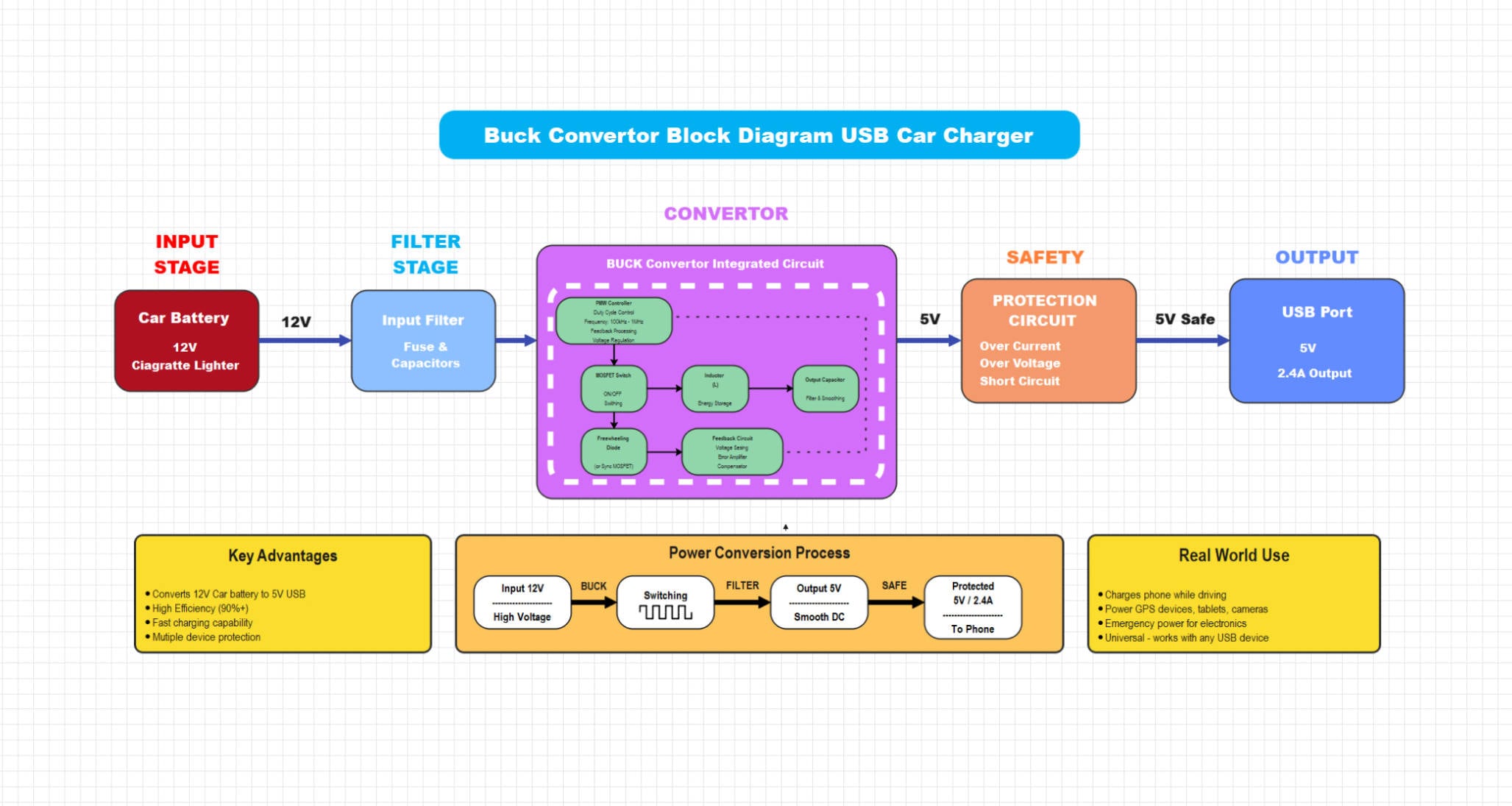
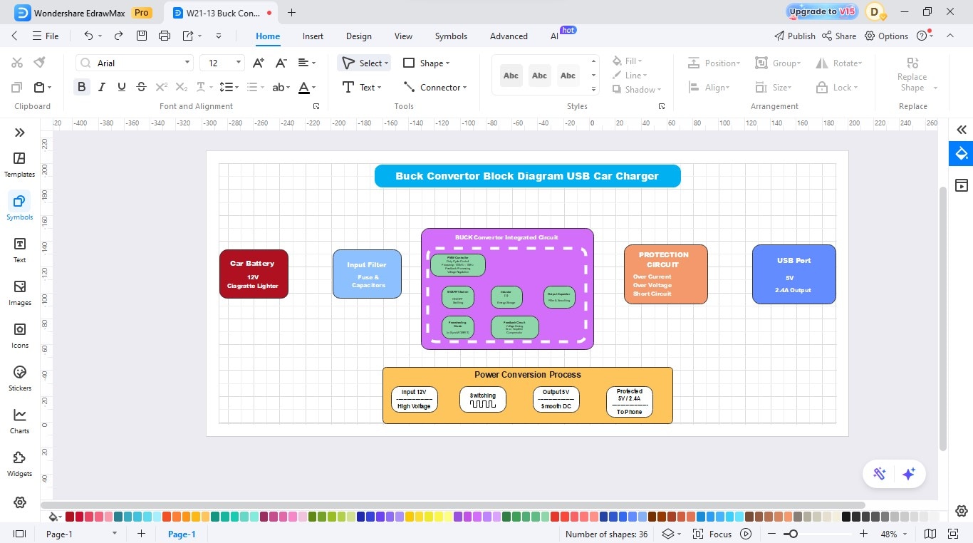
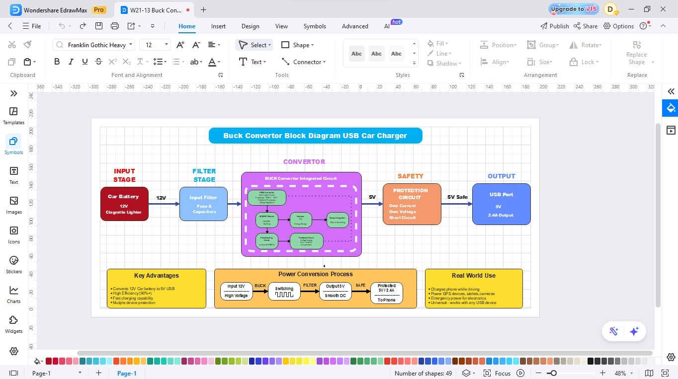
Example 1: Buck Converter Block Diagram – USB Car Charger
This part explains how a 12V car battery is converted into a regulated 5V USB output using a buck converter module. It covers each stage of the system, from the input and filtering stage, where voltage and noise are managed, to the conversion and safety stages, which regulate output voltage and protect against overcurrent or short circuits. The section also discusses real-world efficiency, fast-charging capability, and built-in protection features for portable devices.
This block diagram illustrates a buck converter that steps down 19V DC from a wall adapter to a stable 12V DC output for laptops. The circuit includes PWM control, MOSFET switching, LC filtering, and voltage feedback for regulation. It offers high efficiency, a compact size, and low heat output, making it suitable for laptop and PC power supplies.
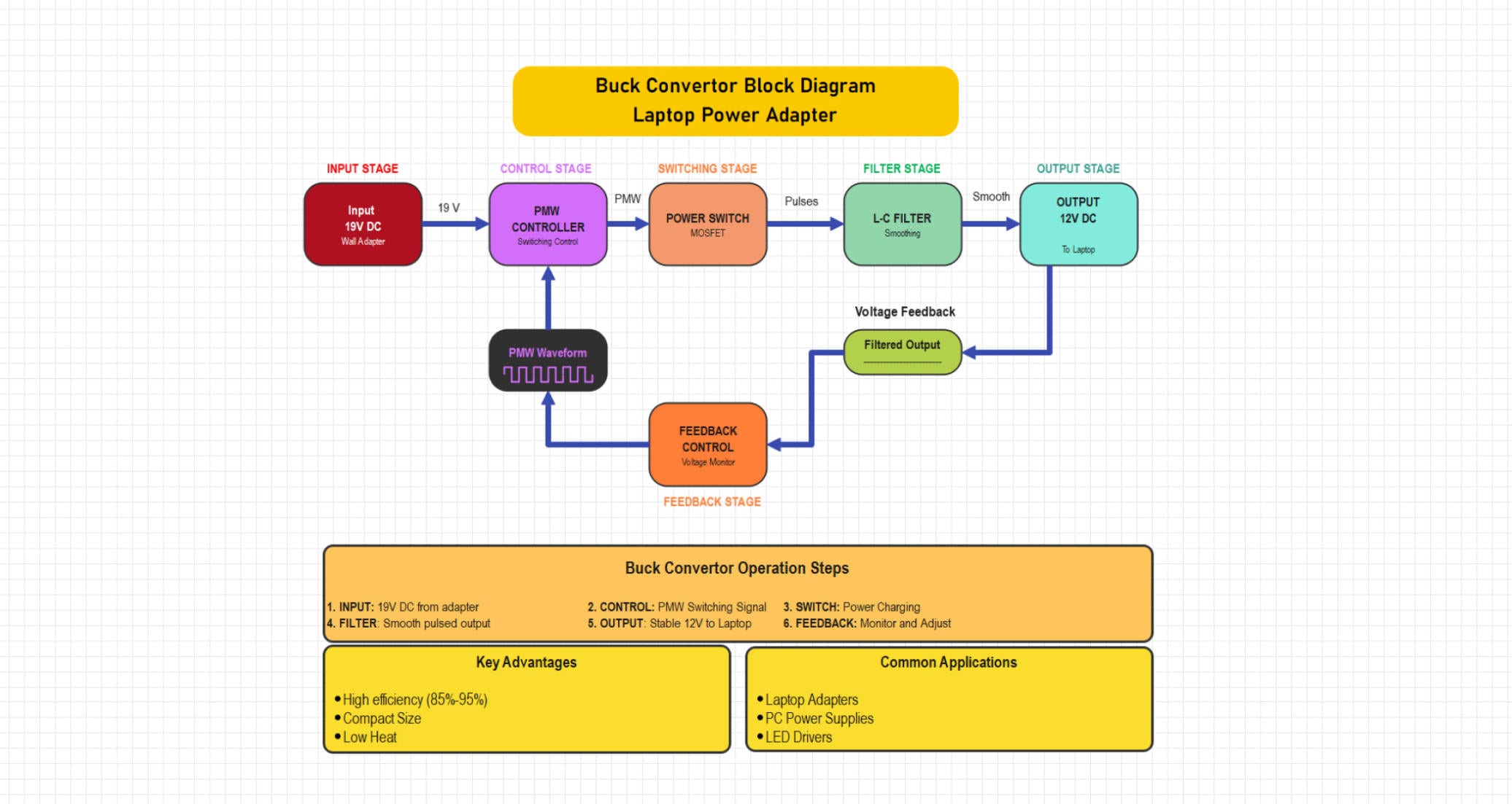
Example 2: Synchronous Buck Converter
Here, the operation of a 19V DC laptop adapter is detailed, showing how it is stepped down to a stable 12V DC output. You’ll learn how the PWM controller, MOSFET switch, and feedback circuit work together to maintain constant voltage under varying loads. The section also highlights the converter’s high efficiency (85–95%), compact design, and applications in laptops, LED drivers, and PC power supplies.
This design converts a 12V car battery input into a 5V regulated USB output using an integrated buck converter IC. The circuit incorporates input filtering, MOSFET switching, feedback control, and a protection stage against overcurrent, overvoltage, and short circuits. It provides fast, efficient, and safe charging for phones and portable devices.
How to Draw a Buck Converter Block Diagram in EdrawMax
Designing a buck converter power supply circuit is effortless with EdrawMax. Its drag-and-drop interface and extensive symbol libraries allow you to quickly add MOSFETs, diodes, inductors, capacitors, and feedback components to create accurate converter diagrams. You can design, customize, and export professional power supply schematics in just a few minutes. Just follow these steps:
Step1 Make a New Project
- Open EdrawMax.
- Click New on the left panel.
- Select Blank Drawing to begin with a blank canvas.

Step2 Select Electronic Symbol Libraries
- Select the left toolbar of Symbols or More Symbols.
- Right-click Manage and then Add More Symbols.
- Add the Electrical or Circuit and Logic libraries to use such components as MOSFETs, diodes, inductors, and capacitors.
Step3 Add the Buck Converter IC and Other Components
- Add an integrated circuit for the Buck Converter.
- Now, add a protection circuit, USB port, and power conversion process block.

Step4 Set the Values in Each Block
- Open each block to identify the parameters that need to be set.
- Modify the values in each block according to the desired output.
Step5 Join the Blocks
- Use the connector tool for joining each block to the next one.
- Ensure the right connections.
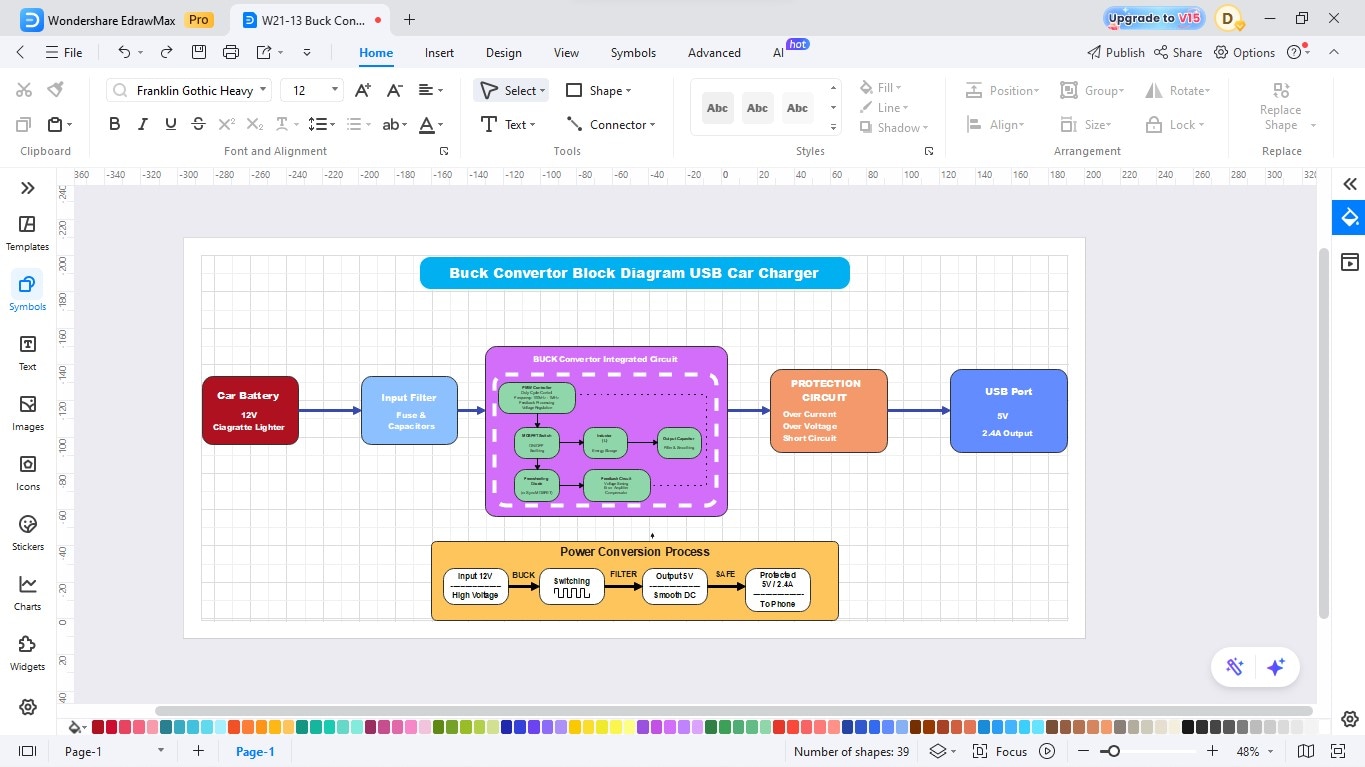
Step6 Label Components and Write a Description
- Name the parts (e.g., USB port, protection circuit).
- Change the colors of the desired element.
- Please write a description or explanation to make it easier to understand.
Step7 Export
- Finalise the diagram by checking the alignment and spacing to ensure it is clear.
- After that, save your design.
- Then export your diagram in the desired format (JPG, PNG, SVG, or PDF).
Create a Circuit Diagram Online Now
EdrawMax is a complete diagramming software that allows the construction of circuit diagrams in a short amount of time and easily by a beginner. Its drag-and-drop platform and huge libraries of components are used to make your circuit look professional without the technical fuss. You can draw, format, and share electrical schematics in minutes, either while studying or working.
Key Features
- Large electronic libraries of symbols of resistors, transistors, ICs, and others.
- Drag-and-drop editor that is intuitive and uses intelligent connectors.
- Collaboration and cloud storage in real time.
- Pre-built templates that are customizable.
- Ability to export a diagram to multiple formats.
Best Practices for Creating Accurate Designs
A properly designed buck converter provides constant voltage, is efficient in operation, and has better longevity. Attention to such important elements and safety precautions can ensure the loss of power, overheating, and unexpected failures.
The following will be some of the tips that you should follow to have a reliable and safe circuit:
Choose the Right values of inductors and Capacitors.
Select an inductor of the correct current rating and inductance to prevent saturation and ripple. Adjust the value of the output capacitor and voltage rating to ensure the output is smooth and minimizes the noise.
Control the frequency and heat of switches.
Increasing the switching frequency will reduce the component size in the space of the components, but will produce more heat. Efficiency frequency: Balance frequency. Balancing frequency to manage thermal accumulation on PCB: using proper heat sinks or copper pours on the PCB.
Add Surge Protection
To absorb voltage spikes and prevent potential bursts to sensitive components, add a snubber across the switch/diode (or a TVS (Transient Voltage Suppression)) diode.
Conclusion
A buck converter design is a good guide to understand and design efficient power supplies. It demonstrates the interaction of every element, switch, diode, inductor, and capacitor, to minimize the voltage and make energy consumption intelligent and constant.
In case you are willing to draw your own diagram, EdrawMax provides fast and professional tools to make your circuit ideas come to life. The drag-and-drop interface and extensive library of symbols allow one to create correct power-supply schematics with ease, even for novices.
AI Diagram Generator
Enter your prompt. Upload files if needed. Generate diagrams, charts, or slides instantly.


