About this network diagram for 4G template
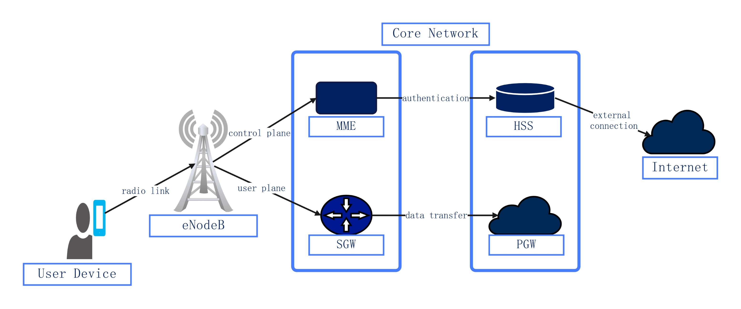
This template maps the essential architecture of a 4G LTE network. It highlights the interaction between user equipment, radio access, and core components. Use this diagram to simplify complex telecommunications concepts for technical presentations or educational documentation.
Radio Access Network (RAN)
The radio access network serves as the initial connection point for mobile users. It consists of the user device and the base station, which manage the physical radio links and signal transmissions across the cell.
- User Device (UE)
- Radio Link Connection
- eNodeB Base Station
Control Plane Management
The control plane handles the logic and security of the network. It manages user mobility, device tracking, and subscriber verification to ensure that only authorized users can access the high-speed data services provided.
- Mobility Management Entity (MME)
- Home Subscriber Server (HSS)
- Authentication Processes
User Plane and Connectivity
The user plane is responsible for routing actual data traffic from the user to the internet. It focuses on high-speed data transfer and serves as the bridge between the internal network and external sources.
- Serving Gateway (SGW)
- PDN Gateway (PGW)
- Data Transfer Path
- External Internet Connection
FAQs about this Template
-
What is the role of the eNodeB in a 4G network?
The eNodeB acts as the primary hardware component in the 4G Radio Access Network. It communicates directly with mobile devices via radio signals. Its main job is to manage radio resources and handle the handovers between different cells. It also separates user data from control signaling, sending each to the appropriate parts of the core network for processing.
-
How does the Core Network ensure user security?
Security is maintained through the collaboration of the MME and the HSS. The HSS stores a central database of all subscriber information and security keys. When a device connects, the MME performs authentication by checking these credentials against the HSS records. This multi-step process prevents unauthorized access and protects the integrity of the communication session across the mobile network.
-
What is the difference between SGW and PGW?
The Serving Gateway (SGW) routes and forwards user data packets while acting as a mobility anchor for the user equipment. In contrast, the Packet Data Network Gateway (PGW) provides the actual connection to external packet data networks like the internet. While the SGW manages internal traffic flow, the PGW handles IP address allocation and policy enforcement for the final connection.